
A mechanical double-knife cutting device with a horizontal spiral feed track

A spiral feed and double-knife cutting technology is applied in metal processing equipment, metal processing machinery parts, manufacturing tools, etc. It can solve the problems of increased tool damage rate and increased tool damage rate, so as to reduce action resistance, Realize the effect of chip blowing heat dissipation and small friction

Active Publication Date: 2020-11-10
福州思琪科技有限公司
View PDF5 Cites 0 Cited by
  • Summary
  • Abstract
  • Description
  • Claims
  • Application Information

AI Technical Summary

Problems solved by technology

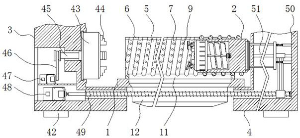
[0003] The structure of the existing cutting lathe has been determined for a long time and has been used until now, that is, the spindle drives the fixture disc to rotate (the fixture disc clamps the workpiece), and the screw rod drives the tool holder to move, and the entire cutting process rotates around the workpiece circle. , The tool holder is moved horizontally. This kind of cutting process does not have much impact on general materials such as aluminum and pure iron, but for hard materials, such as alloy steel and diamond. materials, etc., the damage rate of the tool will be greatly increased. If the operation is not done properly, the damage rate of the tool will also increase.

Method used


Image

  • A mechanical double-knife cutting device with a horizontal spiral feed track
  • A mechanical double-knife cutting device with a horizontal spiral feed track
  • A mechanical double-knife cutting device with a horizontal spiral feed track

Examples


Embodiment Construction

[0031] The following will clearly and completely describe the technical solutions in the embodiments of the present invention with reference to the accompanying drawings in the embodiments of the present invention. Obviously, the described embodiments are only some, not all, embodiments of the present invention.

[0032] In the description of the present invention, unless otherwise stated, the meaning of "plurality" is two or more; the terms "upper", "lower", "left", "right", "inner", "outer" , "front end", "rear end", "head", "tail", etc. indicate the orientation or positional relationship based on the orientation or positional relationship shown in the drawings, and are only for the convenience of describing the present invention and simplifying the description, rather than Nothing indicating or implying that a referenced device or element must have a particular orientation, be constructed, and operate in a particular orientation should therefore not be construed as limiting ...


PUM


Abstract

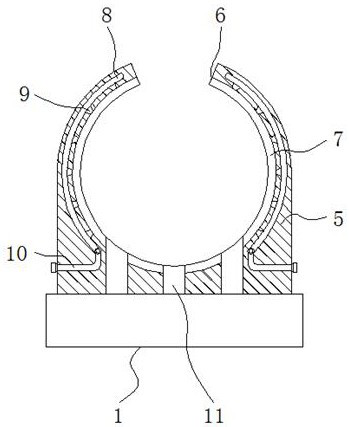
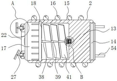
The invention discloses mechanical twin-cutter cutting equipment with a transverse spiral feed rail, and relates to the technical field of mechanical cutting equipment. The mechanical twin-cutter cutting equipment specifically comprises a guide mechanism, a moving mechanism, a front part and a rear part; the inner side of the guide mechanism is provided with the moving mechanism, and one side of the guide mechanism is provided with the front part; the other side of the guide mechanism is provided with the rear part, and the guide mechanism is composed of a guide rail barrel; the inner wall ofthe guide rail barrel is provided with a spiral groove spirally, and the moving mechanism is composed of a support barrel; and the outer wall of the support barrel is fixedly connected with a spiral convex edge. According to the mechanical twin-cutter cutting equipment with the transverse spiral feed rail, in the cutting process, people need to make sure that the rotation direction of a fixture disk is opposite to the rotation direction of the support barrel, so that a tool does rotary feeding or retracting motion relative to a workpiece when the tool is in contact with the workpiece; and thus, the damage rate of the tool is reduced, and the cutting equipment further facilitates improvement of the cutting quality.

Description

technical field [0001] The invention relates to the technical field of mechanical cutting equipment, in particular to a mechanical double-knife cutting equipment with a transverse spiral feed track. Background technique [0002] Among many mechanical processing, cutting is a very common form of processing. In heavy industry, mechanical cutting is a common way of rough processing of plates. It belongs to cold cutting. Its essence is that the metal being processed is squeezed by scissors. In the process of shearing deformation and cracking and separation, cutting is also used for cutting. The cutting form can be divided into milling, turning, boring, grinding, etc. according to different processing and process requirements. The equipment used for various cutting is also Correspondingly, milling machines, lathes, boring machines, grinding machines, etc. are the preferred machines, and modern wire cutting machine tools and electric spark cutting machine tools are also used. As t...

Claims


Application Information

Patent Timeline
Patent Type & Authority Patents(China)
IPC IPC(8): B23Q5/40B23Q11/00B23Q1/25B23Q11/10
CPCB23Q1/25B23Q5/40B23Q11/00B23Q11/005B23Q11/10Y02P70/10
Inventor 包书霞
Owner 福州思琪科技有限公司
Learn More