Floor tile jointing device

A technology for beautifying joints and floor tiles, which is applied in the direction of construction and building construction, can solve the problems of wasting beautifying agents, secondary damage to the edge of floor tiles, and wasting a long time, so as to prevent smearing deviation, regular beautifying joints and beautiful ground Effect

Active Publication Date: 2020-11-20
广州市合抱木建筑技术有限公司
View PDF6 Cites 0 Cited by
  • Summary
  • Abstract
  • Description
  • Claims
  • Application Information

AI Technical Summary

Problems solved by technology

[0002] The laying of floor tiles is an indispensable step in modern home decoration. After the laying is completed, there will be gaps between the floor tiles. The gaps between the floor tiles need to be filled and covered with a beautifying agent; On the one hand, it can effectively prevent moisture from entering the bottom of the floor tiles, and has the effect of waterproofing and anti-mildew. The beautification of floor tiles can be said to be an extremely important step to protect the floor tiles; It is placed on a special glue gun. Due to the large size of the glue gun, it is not convenient to operate; when performing beautification, it is necessary to apply the beautifying agent roughly to the gaps of the floor tiles, and then wait until the beautifying agent is cured. Clean up the excess parts; this operation method is more cumbersome, less efficient and wastes a long time; second, it is easy to cause secondary damage to the edge of the floor tiles when scraping; third, it will waste more beautifying agent; other Fourth, this method of operation is likely to cause the beautifying agent to exist on the surface, resulting in a hollow bottom of the gap, which affects the quality of the beautifying seam; fifth, the uneven thickness of the beautifying seam affects the overall aesthetic feeling of the floor tile; inconveniences and shortcomings

Method used


Image

  • Floor tile jointing device
  • Floor tile jointing device
  • Floor tile jointing device

Examples


Embodiment

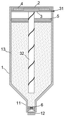
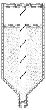
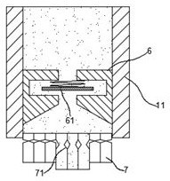
[0020] exist figure 1 , figure 2 , image 3 In the shown embodiment, the local brick beautifying device includes a bottle body 1, a spray pipe 11 and a nozzle 12; the beautifying agent is filled in the bottle body 1; The extrusion part includes a drive plate 2 and a transmission plate 3 arranged at the bottom of the bottle body 1, and the drive plate 2 and the drive plate 3 are arranged in parallel; a ratchet structure is provided on the outer edge of the drive plate 2 with rotational symmetry , a ratchet structure matching the ratchet structure is provided on the inner wall of the bottle body 1 facing the outer edge of the drive disc 2, and the ratchet structure and the ratchet structure are made of elastic materials; the drive disc 3 and the bottle body 1 are slidably connected by a slip ring and a ring groove structure, and the drive plate 3 can rotate freely relative to the bottle body 1; a limit button 31 for limiting the rotation of the drive plate 3 is also provided ...


PUM


Abstract

The invention relates to a floor tile joint sealing device which comprises a bottle body, a nozzle pipe and a nozzle and further comprises a driving disc and a transmission disc disposed at the bottomof the bottle body. An energy storage disc spring is arranged between the driving disc and the transmission disc. A transmission screw is vertically disposed on the transmission disc. A transmissionscrew is sleeved with an extrusion disc spirally. A pressure limiting valve is disposed on the nozzle pipe. The nozzle includes bleed pipes arranged equidistantly in parallel. Each bleed pipe comprises a fixed end, a movable end and a restricting tube connected between the fixed end and the movable end. Each restricting tube comprises symmetrical flaps which are bent towards each other with the gap reduced when the restricting tube is shortened. The floor tile joint sealing device has novel structure and unique principle. A user can conduct floor tile sealing operation easily and quickly, thewaste of raw materials is effectively reduced, the joint sealing efficiency is improved, and the labor intensity is reduced. At the same time, the tile edge is protected, and the effect of regular attractive sealing can be achieved.

Description

technical field [0001] The invention relates to a home improvement tool, in particular to a floor tile beautification tool. Background technique [0002] The laying of floor tiles is an indispensable step in modern home decoration. After the laying is completed, there will be gaps between the floor tiles. The gaps between the floor tiles need to be filled and covered with a beautifying agent; On the one hand, it can effectively prevent moisture from entering the bottom of the floor tiles, and has the effect of waterproofing and anti-mildew. The beautification of floor tiles can be said to be an extremely important step to protect the floor tiles; It is placed on a special glue gun. Due to the large size of the glue gun, it is not convenient to operate; when performing beautification, it is necessary to apply the beautifying agent roughly to the gaps of the floor tiles, and then wait until the beautifying agent is cured. Clean up the excess parts; this operation method is mo...

Claims


Application Information

Patent Timeline
Patent Type & Authority Patents(China)
IPC IPC(8): E04F21/165
CPCE04F21/165
Inventor 朱小菊
Owner 广州市合抱木建筑技术有限公司
Why Eureka
Try Eureka