Flue gas low-temperature desulfurization and denitration spray washing tower

A technology of spray scrubber, desulfurization and denitrification, which is applied in the direction of gas treatment, use of liquid separation agent, combined device, etc., which can solve the problems of short service life of the dust collector bag, prolonging the treatment time of flue gas, and increasing the cost of flue gas treatment , to achieve the effect of reducing cooling and dust removal links, fast denitrification speed, effective cooling and dust removal

Pending Publication Date: 2019-03-29
NANJING GW ENVIRONMENT ENG
View PDF6 Cites 4 Cited by
  • Summary
  • Abstract
  • Description
  • Claims
  • Application Information

AI Technical Summary

Problems solved by technology

[0003] The main problems in the desulfurization and denitrification system in the prior art are: 1. In the prior art, it is usually denitrification first, then dust removal, desulfurization, and then discharge. Usually, the denitrification temperature is 900-1100 degrees Celsius, which is relatively high. The bag filter generally used for dust removal is easily damaged by the flue gas after high-temperature denitrification, resulting in a short service life of the bag filter and poor dust removal effect. It is necessary to cool the desulfurized flue gas in advance to remove dust. On the one hand, after dust removal, it enters the desulfurization tower for desulfurization. The desulfurization temperature is generally 300-400 degrees Celsius. Therefore, the flue gas needs to be effectively cooled after denitrification. This process not only prolongs the time of flue gas treatment, but also leads to the cost of flue gas treatment. improve

Method used


Image

  • Flue gas low-temperature desulfurization and denitration spray washing tower
  • Flue gas low-temperature desulfurization and denitration spray washing tower
  • Flue gas low-temperature desulfurization and denitration spray washing tower

Examples


Embodiment Construction

[0024] The present invention will be further explained below in conjunction with the accompanying drawings and specific embodiments. It should be understood that the following specific embodiments are only used to illustrate the present invention and are not intended to limit the scope of the present invention.

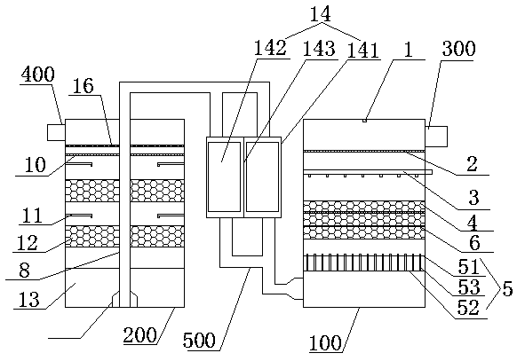
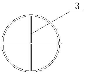
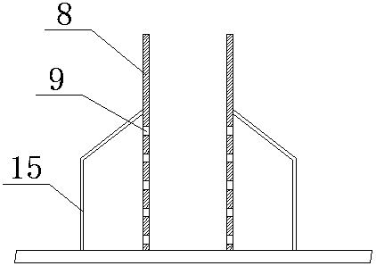
[0025] Such as figure 1 , figure 2 , image 3 As shown, a flue gas low-temperature desulfurization and denitrification spray scrubber includes a denitrification tower 100, a desulfurization tower 200, a smoke inlet pipe 300, and a smoke outlet pipe 400. A flue gas passage pipe 500 is provided between the denitrification tower and the desulfurization tower. The flue gas enters through the flue gas inlet pipe, then desulfurizes in the desulfurization tower, and then enters the desulfurization tower through the flue gas through the pipe for desulfurization, and then the purified flue gas is discharged from the flue gas outlet. Realize rapid and effective denitrificati...


PUM


Abstract

The invention discloses a flue gas low-temperature desulfurization and denitration spray washing tower. The flue gas low-temperature desulfurization and denitration spray washing tower comprises a denitration tower, a desulfurization tower, a flue gas inlet pipeline and a flue gas outlet pipeline. A flue gas passing pipeline is arranged between the denitration tower and the desulfurization tower;a spray water pipe, a flue gas distribution plate, an ammonia spray pipe, a denitration packing chamber and a cooling mixing chamber are arranged from top to bottom in sequence in the denitration tower; and the denitration packing chamber is internally provided with a denitration catalytic plate, and the denitration packing chamber is filled with a filler. A gas inlet pipe is arranged in the center of the desulfurization tower, the gas inlet pipe is connected with the flue gas passing pipeline, and a gas outlet is formed in the bottom of the gas inlet pipe. The desulfurization tower is internally provided with a wind distribution plate, a limewater spray pipe, a desulfurization packing layer and a spray water layer from top to bottom in sequence, and a flue gas outlet pipeline is located above the wind distribution panel. The flue gas low-temperature desulfurization and denitration spray washing tower realizes rapid cooling of flue gas and effective desulfurization, denitrification anddust removal and improves the efficiency of desulfurization and denitration, and the processed flue gas reaches the discharge standard.

Description

technical field [0001] The invention relates to the technical field of flue gas treatment, in particular to a flue gas low-temperature desulfurization and denitrification spray scrubber. Background technique [0002] The desulfurization and denitrification treatment of flue gas is the main process of flue gas treatment at present. The desulfurization and denitrification have been carried out synchronously and integrally. For example, Chinese patent CN201110252739.8 discloses a flue gas purification equipment for small and medium-sized coal-fired boilers, including Desulfurization and dedusting tower and desulfurization and denitrification tower. The desulfurization and denitrification tower is located behind the desulfurization and dedusting tower. The device and the lower flue gas outlet flue, the upper oxidation absorbent injection device includes a spray pipe and a nozzle installed on the spray pipe, the nozzle sprays the oxidation absorbent oxygen H2O2 downward to remove...

Claims


Application Information

Patent Timeline
Patent Type & Authority Applications(China)
IPC IPC(8): B01D53/75B01D53/78B01D53/56B01D53/90B01D53/50B01D53/04B01D50/00B01D47/14B01D47/06
CPCB01D47/06B01D47/14B01D53/04B01D53/502B01D53/75B01D53/78B01D53/8631B01D53/90B01D2251/2062B01D2251/404B01D2258/0283B01D50/60
Inventor 韩正昌马军军孙浩陶志慧黄海峰朱家明张寿兵韩峰吴传宝
Owner NANJING GW ENVIRONMENT ENG
Why Eureka
Try Eureka