High efficient and anti-coking cyclone separator

A technology of cyclone separator and air inlet, which is applied in the direction of cyclone device and the device whose axial direction of the cyclone can be reversed, etc. It can solve the problem of destroying the centrifugal flow field of the separator, unable to completely solve the coking of the separator, and reduce the separation efficiency, etc. problems, to achieve the effect of ensuring long-term safe operation, simple structure, and improving separation efficiency

Inactive Publication Date: 2019-03-29
HEBEI UNIVERSITY OF SCIENCE AND TECHNOLOGY
View PDF6 Cites 3 Cited by
  • Summary
  • Abstract
  • Description
  • Claims
  • Application Information

AI Technical Summary

Problems solved by technology

The above technical solutions all add components in the separator. On the one hand, it will destroy the centrifugal flow field in the separator and reduce the separation efficiency. internal coking problem

Method used


Image

  • High efficient and anti-coking cyclone separator
  • High efficient and anti-coking cyclone separator
  • High efficient and anti-coking cyclone separator

Examples


Embodiment 1

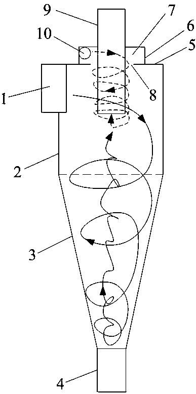
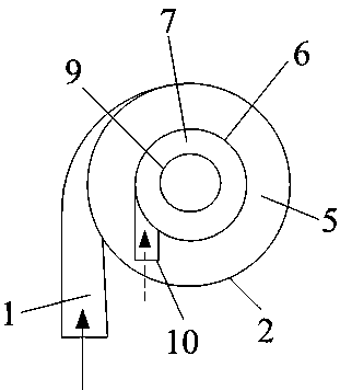
[0022] Embodiment 1: see figure 1 and 2 , the cyclone separator of the present invention consists of a tangential feed port 1, a cylinder body 2, a cone body 3, a material leg 4, a cylinder body top plate 5, a cylinder cavity 6 above the cylinder body, an exhaust pipe 9, and a cylinder cavity The tangential air inlet 10 of the body is formed. The gas carries particles into the separator from the tangential inlet 1, and the clean gas enters the air chamber 7 through the tangential inlet 10 and forms a swirling airflow, enters the separator through the annular gap 8, and rotates downward around the outer wall of the exhaust pipe 9. A rotating air cushion layer is formed on the outer wall of the exhaust pipe, and finally enters the inside of the exhaust pipe through the inlet at the bottom of the exhaust pipe 9 .

Embodiment 2

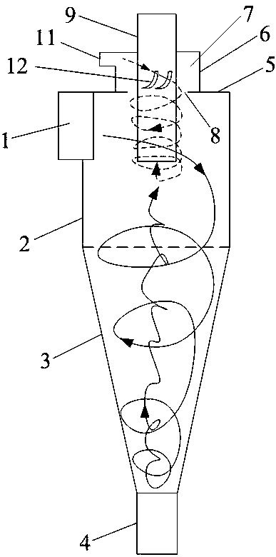
[0023] Example 2: see image 3 and 4 , the cyclone separator of the present invention consists of a tangential feed port 1, a cylinder body 2, a cone body 3, a material leg 4, a cylinder body top plate 5, a cylinder cavity 6 above the cylinder body, an exhaust pipe 9, and a cylinder cavity Body radial air inlet 11, guide vanes 12 constitute. The gas carries particles into the separator from the tangential feed port 1, and the clean gas enters the air chamber 7 through the radial air inlet 11, forms a rotating air flow under the action of the guide vane 12, enters through the annular gap 8 and goes around the exhaust pipe 9 The outer wall rotates downward to form a rotating air cushion layer on the outer wall of the exhaust pipe, and finally enters the inside of the exhaust pipe through the inlet at the bottom of the exhaust pipe 9 .


PUM


Abstract

The invention discloses a cyclone separator capable of preventing particles from being deposited on the outer wall of an exhaust pipe. The problem that the outer wall of an exhaust pipe of the high-temperature cyclone separator is seriously coked is solved, and the cyclone separator is characterized in that a cylinder cavity which is coaxial with the exhaust pipe is arranged above a top plate of the cyclone separator, an air inlet is formed in the side wall of the cavity, and an annular gap is formed between the top plate and the exhaust pipe. According to the cyclone separator, a high-speed rotary air cushion layer formed on the outer wall of the exhaust pipe by using an air flow through the cyclone separator can not only prevent fine particles from adhering and depositing on the outer wall of the exhaust pipe, but also can carry out secondary separation on the fine particles near the outer wall of the exhaust pipe, and the separation efficiency of the small particles can be improvedwhile the coking of the outer wall of the exhaust pipe is overcome.

Description

technical field [0001] The invention relates to a cyclone separator used in the field of solid separation in gas, in particular to a cyclone separator used for the separation of high-temperature solid particle materials. Background technique [0002] The cyclone separator uses the centrifugal force generated by the rotating air flow to separate the solid material from the gas-solid two-phase flow. It has the advantages of simple structure, low cost, easy maintenance, and long-term continuous operation under high temperature and high pressure conditions. It is widely used. It is used in petrochemical, electric power, environmental protection and many other industries, and is a key equipment of petroleum catalytic cracking process, circulating fluidized bed combustion and other production equipment. [0003] In the cyclone separator of the reaction settler of the petroleum catalytic cracking process, there is a cylindrical flow boundary layer on the outer wall of the exhaust p...

Claims


Application Information

Patent Timeline
Patent Type & Authority Applications(China)
IPC IPC(8): B04C5/22B04C5/12
CPCB04C5/12B04C5/22
Inventor 孙占朋彭培英刘庆刚于新奇
Owner HEBEI UNIVERSITY OF SCIENCE AND TECHNOLOGY
Why Eureka
Try Eureka