
Drilling automatic clamping device of double-lug supporting plate nut

A technology of pallet nuts and clamping devices, applied in positioning devices, drilling/drilling equipment, clamping, etc., can solve the problem of inability to meet the requirements of mass automated production, inability to ensure accurate positioning of parts, inability to realize continuous processing, etc. problems, to achieve the effect of realizing large-scale automated production and processing, improving the consistency of product processing, and improving the drilling and processing environment

Inactive Publication Date: 2019-03-29
JIANGXI HONGDU AVIATION IND GRP
View PDF5 Cites 3 Cited by
  • Summary
  • Abstract
  • Description
  • Claims
  • Application Information

AI Technical Summary

Problems solved by technology

[0002] The bottom hole of the threaded nut of the support plate is processed by drilling. The equipment used in manual processing mainly includes a bench drill and a block. The function of the block is to roughly center the nut on the support plate and prevent the parts from rotating. The boss of the nut on the supporting plate is roughly positioned, but the precise positioning of the parts cannot be guaranteed, and it is easy to produce the phenomenon of cutting and winding the drill bit, which cannot realize continuous processing. In addition, there is a phenomenon of cutting fluid splashing around during drilling
The size of the manually processed nuts can still meet the standard requirements, but the processed holes have uneven wall thickness and poor hole diameter consistency, which cannot meet the requirements of mass automated production

Method used


Image

  • Drilling automatic clamping device of double-lug supporting plate nut
  • Drilling automatic clamping device of double-lug supporting plate nut
  • Drilling automatic clamping device of double-lug supporting plate nut

Examples


Embodiment Construction

[0022] In order to make the technical means, creative features, goals and effects achieved by the present invention easy to understand, the present invention will be further described below in conjunction with specific illustrations.

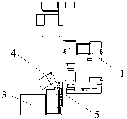
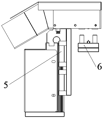
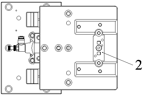
[0023] see Figure 1 to Figure 6 An automatic clamping device for double-ear pallet nut drilling, including double servo power head 1, clamping and positioning mechanism 2, drill cuttings collection box 3, waterproof sheet metal 4, cylinder pressing mechanism 5, and part positioning mechanism 6 , cylinder 7, installation bottom plate 8, vertical plate 9, guide rail slider 10, pressing plate 11, drilling insert 12, cover plate 13, connecting plate 14, drill sleeve 15, pressing column 16, fixing plate 17, positioning Plate 18, positioning insert 19, guide pin 20 and guide post 21; among them, the part positioning mechanism 6 for positioning the double-ear bracket nut is arranged under the double servo power head 1, and is used to guide the drillin...


PUM


Abstract

The invention relates to a drilling automatic clamping device of a double-lug supporting plate nut. A part positioning mechanism used for positioning the double-lug supporting plate nut is arranged below a double-servo power head, a waterproof metal plate used for guiding drilling cuttings into a drilling cuttings collecting box is arranged on the periphery of the upper part of an air cylinder pressing mechanism, the clamping and positioning mechanism is arranged on the upper part of the air cylinder pressing mechanism, and the cuttings collecting box is arranged on one side of the air cylinder pressing mechanism. According to the device, the double-servo drilling power head is adopted for realizing automatic drilling machining of parts, the positioning and clamping modes of the parts areimproved so that the product hole diameter size precision can be improved, the product machining consistency can be effectively improved, and the pneumatic clamping can effectively solve the problem of twining chips around a cutter during cutting; the drilling cuttings collecting box is arranged so as to prevent cutting fluid from splashing, so that the drilling machining environment is improved,meanwhile, the compatibility requirement of multi-model part drilling is met, and large-batch automatic production and machining of the double-lug supporting plate nut can be realized.

Description

technical field [0001] The invention relates to the technical field of mechanical processing, in particular to an automatic clamping device for drilling holes of double-ear bracket nuts. Background technique [0002] The bottom hole of the threaded nut of the support plate is processed by drilling. The equipment used in manual processing mainly includes a bench drill and a block. The function of the block is to roughly center the nut on the support plate and prevent the parts from rotating. The boss of the nut on the supporting plate is roughly positioned, but the precise positioning of the part cannot be guaranteed, and it is easy to cause the phenomenon of cutting and winding the drill bit, which cannot realize continuous processing. In addition, there is a phenomenon of cutting fluid splashing around during drilling. The size of the manually processed nuts can still meet the standard requirements, but the processed holes have uneven wall thickness and poor hole diameter c...

Claims


Application Information

Patent Timeline
IPC IPC(8): B23B47/00B23B49/02B23Q3/08B23Q11/00B23Q11/10
CPCB23B47/00B23B49/02B23Q3/08B23Q11/005B23Q11/10
Inventor 朱裕谱李云花张斌傅勇肖飞王甜杨东彪陈贻强黄长俊周灏蜮袁磊裴立明原鹏飞齐洪豪张如玉
Owner JIANGXI HONGDU AVIATION IND GRP
Learn More