
Stringer-type rail structure capable of drainage

A technology of longitudinal beams and tracks, applied in the field of longitudinal beam track structures, can solve problems such as uneven deformation of track structures, endangering driving safety, insufficient rigidity, etc., and achieve the effects of preventing water damage, simple structure, and easy replacement and maintenance

Pending Publication Date: 2019-03-29
CENT SOUTH UNIV
View PDF2 Cites 0 Cited by
  • Summary
  • Abstract
  • Description
  • Claims
  • Application Information

AI Technical Summary

Problems solved by technology

[0003] The present invention provides a drainable longitudinal beam track structure aiming at the deficiencies of the prior art, which solves the problem of uneven deformation of the track structure caused by insufficient rigidity of the track structure in the tunnel, thereby endangering driving safety and difficulty in drainage, resulting in muddying. question

Method used


Image

  • Stringer-type rail structure capable of drainage
  • Stringer-type rail structure capable of drainage
  • Stringer-type rail structure capable of drainage

Examples


Embodiment 1

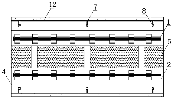
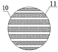
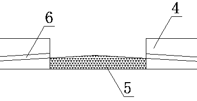
[0025] A drainable longitudinal beam track structure, comprising a steel rail 1, a longitudinal beam sleeper 2 at the lower part of the rail 1, a shock-absorbing pad 3 is arranged between the longitudinal beam sleeper 2 and a lower concrete base 4, and the concrete base 4 Set up a horizontal drainage pipe 6, and set up a herringbone rail fill 5 between the concrete bases 4 on both sides to leave seepage water, and drain the accumulated water around the track to the tunnel side trench 9 on both sides through the horizontal drainage pipe 6 and PVC pipe 7 To go, the horizontal drain pipe 6 and the PVC pipe 7 are connected by a sleeve 8. A PE fence 10 is installed at the entrance of the horizontal drainage pipe 6, and the PE fence 10 can prevent the coal lump scattered during transportation from flowing into the horizontal drainage pipe 6 with water and block the horizontal drainage pipe 6.

Embodiment 2

[0027] A drainable longitudinal beam track structure, comprising a steel rail 1, a longitudinal beam sleeper 2 at the lower part of the rail 1, a shock-absorbing pad 3 is arranged between the longitudinal beam sleeper 2 and a lower concrete base 4, and the concrete base 4 Set up a horizontal drainage pipe 6, and set up a herringbone rail fill 5 between the concrete bases 4 on both sides to leave seepage water, and drain the accumulated water around the track to the tunnel side trench 9 on both sides through the horizontal drainage pipe 6 and PVC pipe 7 To go, the horizontal drain pipe 6 and the PVC pipe 7 are connected by a sleeve 8. A PE fence 10 is installed at the entrance of the horizontal drainage pipe 6, and the PE fence 10 can prevent the coal lump scattered during transportation from flowing into the horizontal drainage pipe 6 with water and block the horizontal drainage pipe 6. A long-fiber hot-tie non-woven fabric 11 is arranged inside the PE fence 10, and the long-fi...


PUM


Abstract

The invention discloses a stringer-type rail structure capable of drainage, and belongs to the technical field of rail structures. The soil rising problem caused by insufficient hardness of a rail structure inside a tunnel and delayed drainage is solved. The stringer-type rail structure includes steel rails, stringer-type rail supports, damping mat layers, concrete bases and inverted-Y-shaped inter-rail filler. Transverse drainage pipes are arranged inside the concrete bases, and side ditches are formed in the two sides; PE fences and long-fiber hot-rolling nonwoven fabric are arranged at water inlets of the drainage pipes; the water outlets of the drainage pipes are connected with PVC pipes through sleeve cylinders. By adopting the stringer-type rail structure capable of drainage, the bending resistance stiffness of the rail structure is improved, and retained water inside the tunnel can be drained in time; the stringer-type rail structure is simple in structure and convenient to maintain and replace, and the operation safety of a train inside the tunnel is improved.

Description

Technical field [0001] The invention belongs to the technical field of track structures, and particularly relates to a drainable longitudinal beam type track structure. Background technique [0002] The track in the Daqin line tunnel currently adopts the traditional "wide sleeper" structure. Due to the large axle load of the freight train, the existing track structure due to its insufficient rigidity leads to uneven settlement of the track structure in the tunnel. At the same time, because a large amount of coal dust will be scattered during the coal transportation line, in a relatively closed space such as a tunnel, most of the coal dust will accumulate in the gaps of the ballast, resulting in the accumulation of water inside the tunnel not being able to pass through in time The ballast drains away, and the mud and mud phenomenon is particularly serious. These phenomena pose a great threat to driving safety. Summary of the invention [0003] In view of the shortcomings of the p...

Claims


Application Information

Patent Timeline
IPC IPC(8): E01B1/00E21F16/02
CPCE21F16/02E01B1/008E01B2204/07
Inventor 汪优任加琳李奕金
Owner CENT SOUTH UNIV
Learn More