Roof photovoltaic power generation station structure and lap joint method thereof

A photovoltaic power station and roof panel technology, applied in photovoltaic power generation, photovoltaic module support structure, roof and other directions, can solve the problems of poor sealing, insufficient corrosion resistance and high maintenance cost of roof photovoltaic power station, so as to reduce the construction cost and The effect of maintenance cost, weight reduction and high roof strength

Pending Publication Date: 2019-03-29
湖北中复能新型材料有限公司
View PDF0 Cites 4 Cited by
  • Summary
  • Abstract
  • Description
  • Claims
  • Application Information

AI Technical Summary

Problems solved by technology

[0008] The embodiment of the present invention provides a roof photovoltaic power station structure and its lapping method, which are used to solve the problems of poor sealin

Method used


Image

  • Roof photovoltaic power generation station structure and lap joint method thereof
  • Roof photovoltaic power generation station structure and lap joint method thereof
  • Roof photovoltaic power generation station structure and lap joint method thereof

Examples


Embodiment 1

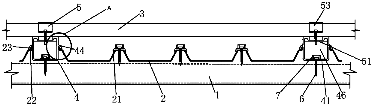
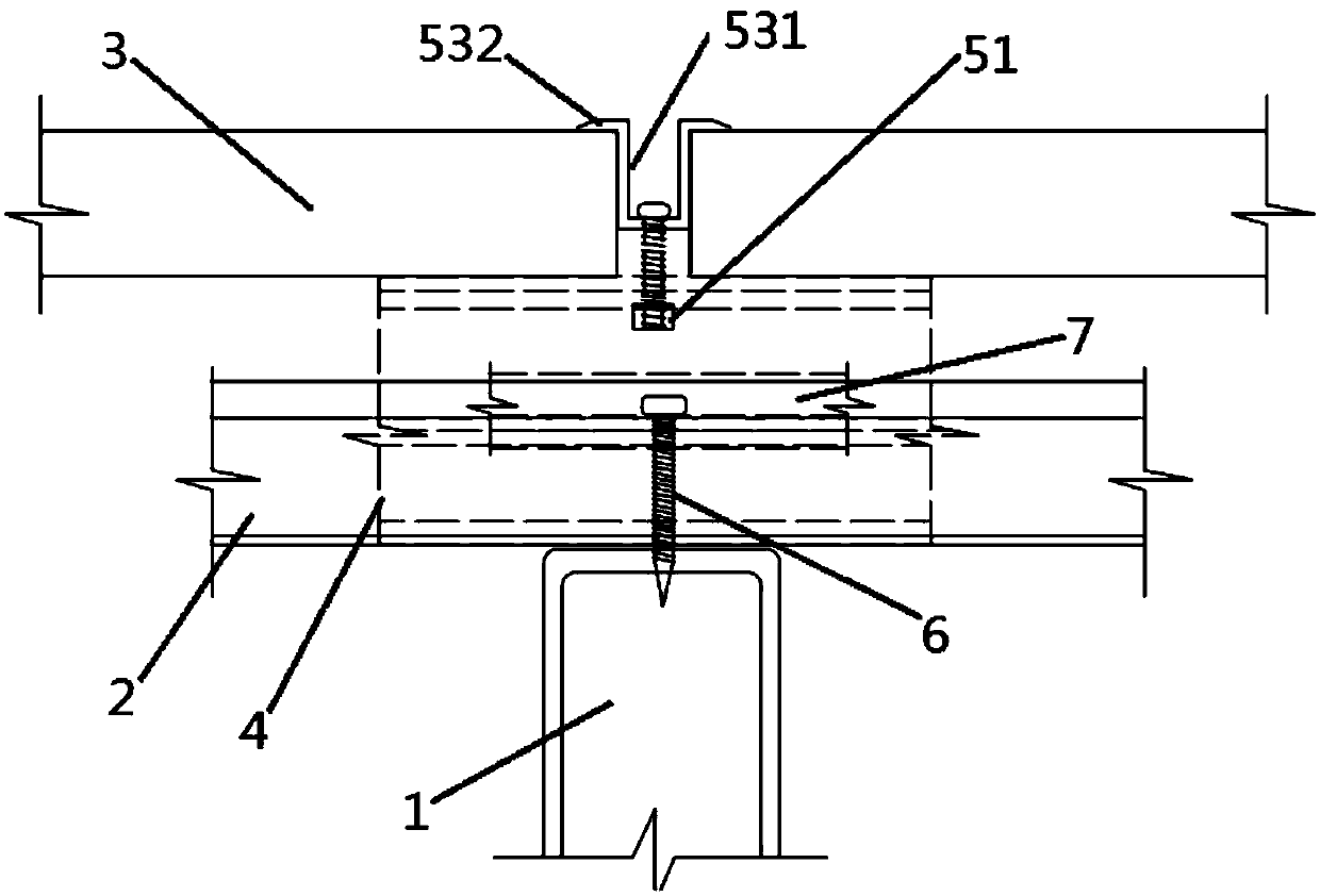
[0047] This embodiment provides a roof photovoltaic power station structure, such as figure 1 , figure 2 As shown, the roof photovoltaic power station structure includes a purlin 1 , a roof panel 2 , a photovoltaic panel 3 , a positioning mechanism 4 and a locking mechanism 5 .

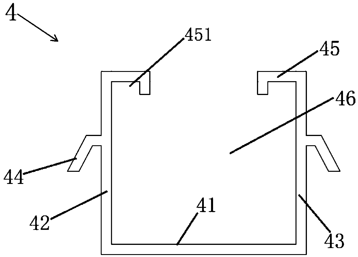
[0048] like image 3 As shown, the positioning mechanism 4 includes a bottom plate 41 , a left side plate 42 , a right side plate 43 , a flange 44 and a flange 45 . The left side plate 42 and the right side plate 43 are vertically arranged on the top surface of the bottom plate 41 to form a through groove 46, the flange 44 is arranged on the outer wall of the left side plate 42 and the right side plate 43, and the flange 45 is arranged on the left side plate 42 and the inner wall of the right side panel 43, the flange 44 is clamped and fixed with the edge of the roof panel 2, and the bottom panel 41 is fixed on the purlin 1.

[0049] In this embodiment, the flange 44 is arranged on the middle part...

Embodiment 2

[0056] like figure 1 , figure 2 As shown, the structure of this embodiment is basically the same as that of Embodiment 1. The structure of the roof photovoltaic power station provided by this embodiment also includes self-tapping screws 6 and waterproof fasteners 7, and a through hole is provided on the surface of the bottom plate 41 through its thickness. The tapping screw 6 passes through the through hole to fix the bottom plate 41 on the purlin 1, and the waterproof fastener 7 is covered on the nail cap of the self-tapping screw 6 to protect the self-tapping screw 6 and prevent rainwater from corroding the self-tapping screw 6. The fastening combination of the bottom plate 41 and the purlin 1 .

Embodiment 3

[0058] like figure 1 , figure 2 , Image 6 As shown, the structure of this embodiment is basically the same as that of Embodiment 1. In the roof photovoltaic power station structure provided by this embodiment, the roof panel 2 includes corrugated 21, water-stop ribs 22 and sealing rubber strips 23, and the corrugated 21 is along the roof panel 2. The width direction is arranged at intervals, and the water-stop ribs 22 are arranged at the ends of the roof panel 2 in the length direction. The water-stop ribs 22 extend upwards and outwards. 23 is arranged on the upper surface of the water-stop rib 22 and is crimped and fixed by the flange 44 .

[0059] In this embodiment, the total width of the roof panel 2 is 835 mm, the thickness of the board is 2.5 mm, there are five corrugated 21, the height of the corrugated 21 is 35 mm, and the interval between each corrugated 21 is 195 mm.

[0060] In this embodiment, the rigidity of the roof panel 2 is enhanced by arranging the corru...


PUM


Abstract

The embodiment of the invention discloses a roof photovoltaic power generation station structure and a lap joint method thereof. The structure comprises a purline, a roof plate, a photovoltaic plate,a positioning mechanism and a locking mechanism. The positioning mechanism comprises a bottom plate, a left side plate, a right side plate, a wing and a flange. The locking mechanism comprises a clamping part, a fastener and a fixing part. The positioning mechanism and the locking mechanism have the effect of fixing the roof plate and the photovoltaic plate respectively. The positioning mechanismhas the fixing effect and meanwhile serves as a main load-bearing carrier of the roof photovoltaic power generation station structure. Thus, the roof photovoltaic power generation station structure has the good sealing performance, waterproof performance, corrosion resistance and thermal insulation performance and is long in service life and low in maintenance cost; the lap joint method is simplein process, safe in operation and suitable for wide use and popularization, local maintenance can be realized, and maintenance is convenient.

Description

technical field [0001] The embodiment of the present invention relates to the field of photovoltaic technology, in particular to a roof photovoltaic power station structure and its overlapping method Background technique [0002] Distributed photovoltaic power generation refers to a power generation method that uses photovoltaic modules to directly convert solar energy into electrical energy. At present, the most widely used method of distributed photovoltaic power generation is to build roof distributed photovoltaic power stations. Due to the high power consumption and large single building area of ​​industrialized steel structure workshops for industrial production, building distributed photovoltaic power stations on the roof of steel structure workshops can make full use of local solar energy resources, reduce or even replace the consumption of fossil energy, Achieve the effect of green environmental protection and reduce energy consumption. [0003] However, most of th...

Claims


Application Information

Patent Timeline
IPC IPC(8): E04D3/36E04D13/18E04D3/38H02S20/23
CPCE04D3/36E04D3/38H02S20/23Y02B10/10Y02B10/20Y02E10/50
Inventor 庄华山
Owner 湖北中复能新型材料有限公司
Why Eureka
Try Eureka