
Single-frequency laser interferometer nonlinear error correction method and device thereof

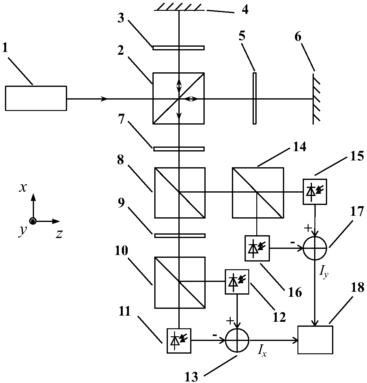
A non-linear error and single-frequency laser technology, applied in the direction of optical devices, measuring devices, instruments, etc., can solve the problems of affecting the position stability of the first mirror, increasing the complexity of the system and control, and increasing the volume of the device. Achieve the effects of reducing system volume and complexity, suppressing phase delay drift, and simplifying operation steps

Pending Publication Date: 2019-03-29
HARBIN INST OF TECH
View PDF7 Cites 12 Cited by
  • Summary
  • Abstract
  • Description
  • Claims
  • Application Information

AI Technical Summary

Problems solved by technology

But this method also has certain problems: additional motion control components increase the complexity of the system and control, and inevitably affect the position stability of the first mirror, thus introducing measurement errors
However, this method also has certain defects: first, this method can only obtain the DC offset error and unequal amplitude error parameters in the triple difference of the characteristic parameters of the interference signal, but cannot obtain the non-orthogonal error parameters, so it is necessary to Measurement can only be carried out with a specific interference optical path structure, which is not universal; secondly, this method requires two optical switches, which leads to an increase in the size of the device, and requires multiple operations on the two optical switches, and the steps are complicated

Method used


Image

  • Single-frequency laser interferometer nonlinear error correction method and device thereof
  • Single-frequency laser interferometer nonlinear error correction method and device thereof
  • Single-frequency laser interferometer nonlinear error correction method and device thereof

Examples


Embodiment Construction

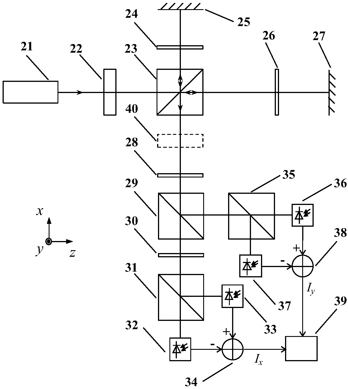
[0028] Since the single-frequency interferometer itself has different forms of optical path structure, the following is figure 2 The embodiment of the present invention will be described in detail by taking the two-subdivision optical path single-frequency interferometer composed of a polarization beam splitter prism and a plane mirror as an example.

[0029] A single-frequency laser interferometer nonlinear error correction device based on a liquid crystal phase retarder, the device includes a single-frequency laser 21, a liquid crystal phase retarder 22, a polarization beam splitter A 23, a 1 / 4 wave plate A 24, a first reflector Mirror 25, 1 / 4 wave plate B 26, second mirror 27, 1 / 2 wave plate 28, non-polarizing beam splitting prism 29, 1 / 4 wave plate C 30, polarizing beam splitting prism B 31, photodetector A 32, Photodetector B 33, subtractor A 34, polarization beamsplitter prism C 35, photodetector C 36, photodetector D 37, subtractor B 38; polarization beamsplitter prism...


PUM


Abstract

A single-frequency laser interferometer nonlinear error correction method and a device thereof belong to the field of laser measurement technology. According to the method of the invention, under a precondition that the position of a first reflector and the position of a second reflector are unchanged, a liquid crystal phase delayer is used for generating a continuous light path difference changebetween a measuring light beam and a reference light beam, so that an enough phase change of an interference signal is generated, and pre-extraction for the characteristic parameter of the interference signal is realized, thereby correcting a nonlinear error in the displacement measurement process of the single-frequency laser interferometer by means of the pre-extracted characteristic parameter,and realizing high-precision displacement measurement. The single-frequency laser interferometer nonlinear error correction method and the device thereof realize pre-extraction for the characteristicparameter of the interference signal of the single-frequency laser interferometer and can effectively settle a problem of correcting the nonlinear error in interference measurement, particularly mini-displacement measurement. The method and the device thereof have substantial technical advantages in the precise measurement field.

Description

technical field [0001] The invention belongs to the technical field of laser measurement, and mainly relates to a method and device for correcting nonlinear errors of a single-frequency laser interferometer. Background technique [0002] With the rapid development of scientific research and the rapid improvement of industrial production levels, scientific research and industrial fields have also put forward higher requirements for displacement measurement, and the minimum change of displacement measurement is also developing towards the nanometer level. Single-frequency laser interferometry is an instrument for high-precision displacement measurement using the principle of laser interferometry. It has the advantages of non-contact and high precision. A single-frequency laser interferometer includes at least one light source capable of providing a single-frequency laser; a polarization beam splitter that divides the single-frequency light source into a reference beam and a me...

Claims


Application Information

Patent Timeline
IPC IPC(8): G01B9/02G01B11/02
CPCG01B9/0201G01B9/02058G01B11/02
Inventor 胡鹏程付海金王珂谭久彬
Owner HARBIN INST OF TECH
Learn More