Combined calibration method for EPS zero offset and multi-line laser radar

A lidar, multi-line laser technology, applied in radio wave measurement systems, instruments, etc., can solve problems such as low efficiency, high sensor accuracy requirements, and immature autonomous driving.

Active Publication Date: 2019-03-29
BEIJING ZHIXINGZHE TECH CO LTD
View PDF17 Cites 26 Cited by
  • Summary
  • Abstract
  • Description
  • Claims
  • Application Information

AI Technical Summary

Problems solved by technology

[0003] Among the existing technologies, related technologies in the field of autonomous driving are not yet mature
Especially in electric power steering system (Electric Power Steering, EPS) zero offset calibration and multi-line lidar installation angle calibration technology, there is no very efficient and accurate calibration method
In the prior art, both EPS zero bias and multi-line lidar are calibrated separately. The disadvantages are low calibration accuracy, high precision requirements for reference equipment or sensors, long time consumption, and low efficiency.
Moreover, the current calibration method is implemented manually or by calibration objects. Due to the different colors and materials of the calibration objects, their reflectivity is also different, making the calibration results inaccurate.

Method used


Image

  • Combined calibration method for EPS zero offset and multi-line laser radar
  • Combined calibration method for EPS zero offset and multi-line laser radar
  • Combined calibration method for EPS zero offset and multi-line laser radar

Examples


Embodiment Construction

[0037] In order to make the object, technical solution and advantages of the present invention clearer, the present invention will be further described in detail below in conjunction with the accompanying drawings. Obviously, the described embodiments are only some embodiments of the present invention, rather than all embodiments . Based on the embodiments of the present invention, all other embodiments obtained by persons of ordinary skill in the art without making creative efforts belong to the protection scope of the present invention.

[0038] The vehicle in the technical solution of the present invention is a self-driving vehicle. The control of each module and information interaction with the server are realized through the vehicle-mounted terminal, and the surrounding environment can be sensed through sensors such as laser radar, ultrasonic radar, millimeter-wave radar, and camera, and automatic driving can be realized. Drive to the designated place according to the pre...


PUM


Abstract

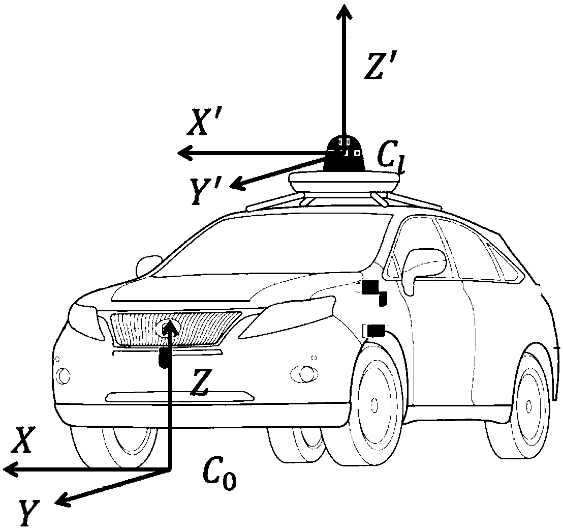
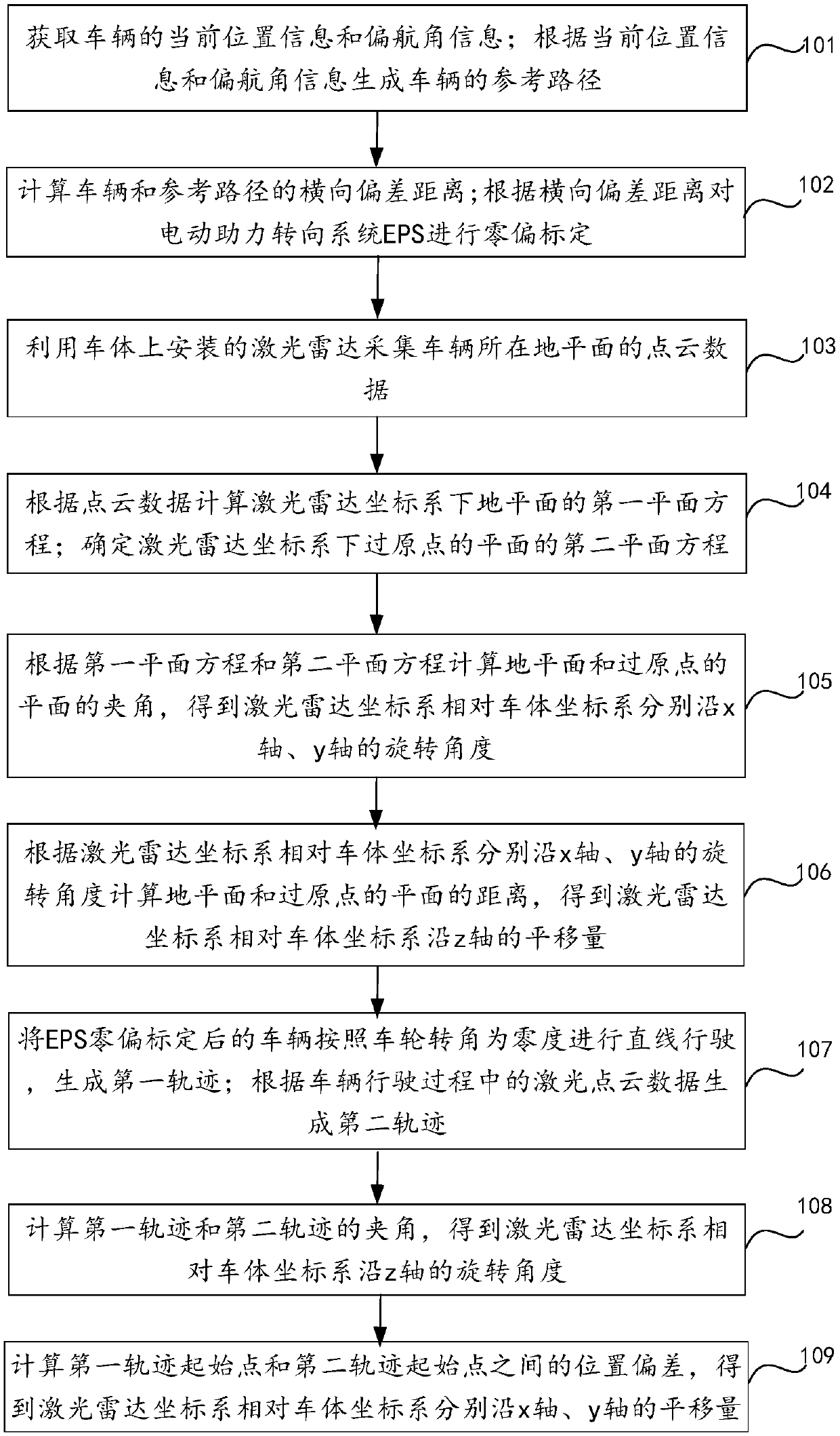
The invention relates to a combined calibration method for an EPS (Electric Power Steering) zero offset and a multi-line laser radar. The method comprises the following steps: obtaining current position information, yaw angle information, and a reference path of a vehicle; calculating a lateral offset distance of the vehicle and the reference path; performing zero-offset calibration on the EPS; calculating an included angle and a distance between the ground plane and a plane crossing an origin to obtain an rotation angle of a laser radar coordinate system relative to a vehicle body coordinatesystem along the x axis and the y axis, and a shift amount along the z axis; performing linear driving on the vehicle after EPS zero offset calibration taking the wheel angle as zero degree to generate a first trajectory; generating a second trajectory according to laser point cloud data in the vehicle driving process; calculating the included angle of the first trajectory and the second trajectory to obtain the rotation angle of the laser radar coordinate system relative to the vehicle body coordinate system along the z-axis; and calculating a position deviation between a starting point of the first trajectory and the starting point of the second trajectory to obtain the shift amount of the laser radar coordinate system relative to the vehicle body coordinate system along the x-axis and the y-axis respectively.

Description

technical field [0001] The invention relates to the technical field of automatic driving, in particular to a joint calibration method of EPS zero bias and multi-line laser radar. Background technique [0002] With the development of the economy and the rise of artificial intelligence technology, self-driving cars are getting more and more attention from the market. Self-driving cars refer to relying on the cooperation of artificial intelligence, visual computing, radar, monitoring devices and global positioning systems, so that computers can automatically and safely operate motor vehicles without any active human operation. The market predicts that the popularization of self-driving cars can reduce the incidence of traffic accidents, reduce traffic congestion, reduce the cost of investing in transportation infrastructure, and reduce environmental pollution. [0003] In the existing technology, the relevant technologies in the field of autonomous driving are not yet mature. ...

Claims


Application Information

Patent Timeline
Patent Type & Authority Applications(China)
IPC IPC(8): G01S7/497
CPCG01S7/497
Inventor 张德兆王肖李晓飞张放霍舒豪
Owner BEIJING ZHIXINGZHE TECH CO LTD
Why Eureka
Try Eureka