
Magnetic core assembly for high-frequency transformer and high-frequency transformer

A high-frequency transformer and magnetic core technology, applied in the direction of transformer/inductor magnetic core, transformer/inductor parts, electrical components, etc., can solve high-frequency eddy current loss, transformer working flux and inductance influence, magnetic circuit Problems such as large dispersion of parameters can achieve the effects of reducing operating temperature rise, eliminating eddy current loss, and eliminating leakage magnetic flux

Inactive Publication Date: 2019-03-29
JIANGSU WANBANG DEHE NEW ENERGY TECH CO LTD
View PDF3 Cites 0 Cited by
  • Summary
  • Abstract
  • Description
  • Claims
  • Application Information

AI Technical Summary

Problems solved by technology

Although the increase of the air gap in the magnetic core meets the above design requirements, it also has the following disadvantages: the magnetic flux at the air gap leaks, passes through the adjacent windings, and generates high-frequency eddy current losses in the windings
The usual way to solve the additional loss of the air gap is to replace the large air gap with multiple small air gaps. Although this method can reduce the air gap, the additional loss caused by the leakage magnetic flux cannot be eliminated, and it also increases the complexity of the transformer production process.
In addition, small changes in the air gap have a significant impact on the working flux and inductance of the transformer. Because the air gap accuracy of the magnetic circuit air gap processing and assembly process is not easy to control, it often leads to large dispersion of the magnetic circuit parameters.

Method used


Image

  • Magnetic core assembly for high-frequency transformer and high-frequency transformer
  • Magnetic core assembly for high-frequency transformer and high-frequency transformer

Examples


Embodiment 1

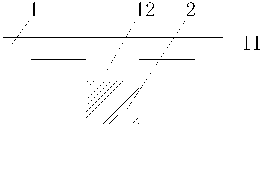
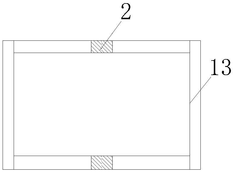
[0022] to combine figure 1 , a high-frequency transformer magnetic core assembly proposed by the present invention, the magnetic core assembly includes two magnetic core bodies 1 and an auxiliary magnetic core body 2, the two magnetic core bodies 1 are connected to the auxiliary magnetic core body 2, and Cooperating to form a closed magnetic circuit without an air gap, the magnetic permeability of the magnetic core body 1 is greater than that of the auxiliary magnetic core body 2 .

[0023] The magnetic core body 1 can be made of a material with a relatively high magnetic permeability, such as manganese zinc ferrite, and the magnetic core body 1 can be made of a material with a small magnetic permeability, such as sendust and hydroxy iron powder.

[0024] The magnetic core body 1 is the main body material of the magnetic core assembly, which accounts for most of the volume of the magnetic core. Auxiliary sub-cores are auxiliary materials that occupy a small portion of the vol...

Embodiment 2

[0031] The difference between this embodiment and Embodiment 1 is that this embodiment discloses a high-frequency transformer, including a bobbin, a winding coil, and a high-frequency transformer core assembly. The high-frequency transformer core assembly in this embodiment is the same as that in the embodiment The core components of the high-frequency transformer in 1 are exactly the same, so they will not be repeated here to save space.


PUM


Abstract

The invention provides a magnetic core assembly for a high-frequency transformer. The magnetic core assembly comprises a magnetic core main body and an auxiliary magnetic core body, wherein the magnetic core main body is connected with the auxiliary magnetic core body and is matched with the auxiliary magnetic core body to form a closed magnetic circuit without an air gap, and the magnetic conductivity of the magnetic core main body is larger than that of the auxiliary magnetic core body. A magnetic material with relatively low magnetic conductivity is used for replacing an air gap, and due tothe fact that no air gap exists in the whole magnetic circuit, dispersed and leaked magnetic flux of the air gap is thoroughly eliminated, air gap dispersed and leaked magnetic flux eddy current lossin high-frequency application is eliminated, the efficiency of a transformer is effectively improved, and the operation temperature rise is reduced.

Description

technical field [0001] The invention relates to the field of magnetic cores, in particular to a high-frequency transformer magnetic core assembly and a high-frequency transformer. Background technique [0002] In high-frequency transformers, in order to meet the requirements of energy storage, suppression of magnetic core saturation, or adjustment of inductance, it is usually necessary to open one or more air gaps on the magnetic core. Although the increase of the air gap in the magnetic core meets the above design requirements, it also has the following disadvantages: the magnetic flux at the air gap leaks, passes through the adjacent windings, and generates high-frequency eddy current losses in the windings. This additional eddy current loss increases the power dissipation of the transformer, increases the operating temperature rise, and reduces the efficiency of the transformer. As the switching frequency increases, the additional high-frequency eddy current losses near ...

Claims


Application Information

Patent Timeline
IPC IPC(8): H01F27/24H01F27/34H01F27/38
CPCH01F27/24H01F27/346H01F27/38H01F2027/348
Inventor 牛坤宏邵丹薇杨志李德胜
Owner JIANGSU WANBANG DEHE NEW ENERGY TECH CO LTD
Learn More