

Method for manufacturing transparent flexible capacitor with high quality factor
A high-quality factor, capacitor technology, applied in the direction of laminated capacitors, fixed capacitor electrodes, fixed capacitor parts, etc., can solve the problems of low square resistance, long service life of capacitors, large leakage current of capacitors, etc., and achieve excellent bending performance , long service life and stable performance
- Summary
- Abstract
- Description
- Claims
- Application Information
AI Technical Summary
Problems solved by technology
Method used
Image

Examples
Embodiment 1
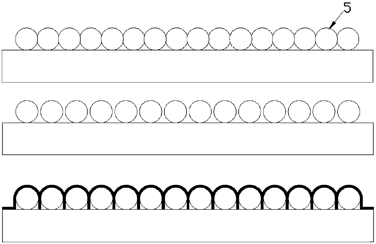
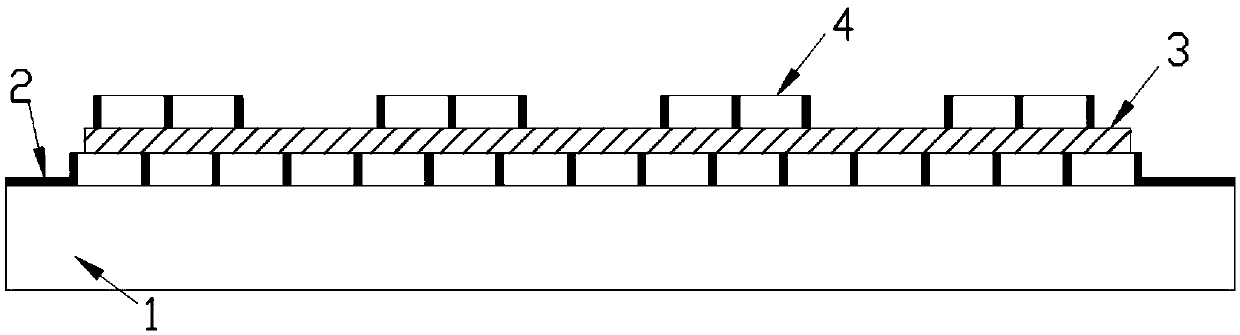
[0037] The PS ball with a diameter of 3um is selected, but the diameter of the PS ball is not limited to 3um. The self-assembly feature is used to pave the surface on a 2-inch plastic substrate PET. Subsequently, the ball shrinking process is carried out using reactive ion rapid etching technology to expand the gap between the balls. Then, chromium-gold with a thickness of 80nm is deposited on the PS ball template by thermal evaporation, and then the PS ball template is removed by chemical etching, leaving a nano-network formed by the metal in the gap between the ball and the ball. The prepared metal nanomesh is used as the bottom electrode of the transparent flexible capacitor; at 300℃, 15nm ZrO is grown on the metal nanomesh electrode by atomic layer deposition technology 2 As the dielectric layer of the transparent flexible capacitor; then the metal nano mesh is prepared on the dielectric layer as the top electrode by the same method as described above. Finally, the top elec...
Embodiment 2
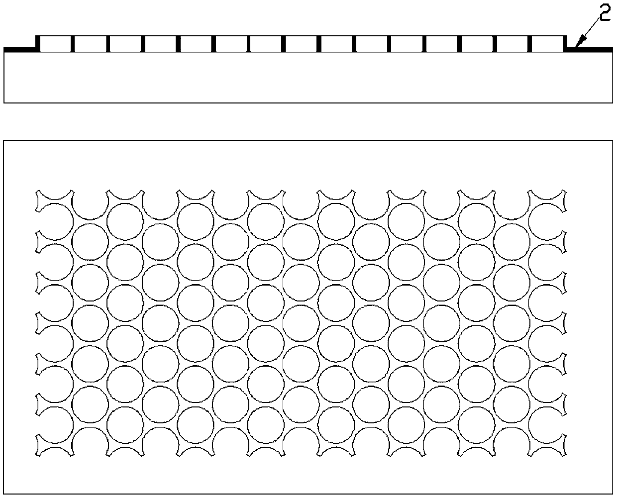
[0039] The PS ball with a diameter of 3um is selected, but the diameter of the PS ball is not limited to 3um. The self-assembly feature is used to pave it on a 2-inch plastic substrate PEN. Subsequently, the ball shrinking process is carried out using reactive ion rapid etching technology to expand the gap between the balls. Then use thermal evaporation to deposit 80nm thick chromium gold on the PS ball template, and then use the chemical etching method to remove the PS ball template, leaving the gap between the balls and the metal connected nano mesh, metal nano mesh The preparation process of the shaped electrode is as figure 1 Shown. The prepared metal nano mesh is used as the bottom electrode of transparent flexible capacitor, such as figure 2 Shown; At 300 ℃, using atomic layer deposition technology to grow 15nm ZrO on the metal nano mesh electrode 2 As the dielectric layer of the transparent flexible capacitor; then the metal nano mesh is prepared on the dielectric layer...
Embodiment 3
[0041] A PS ball with a diameter of 950nm is selected, but the diameter of the PS ball is not limited to 950nm. The self-assembly feature is used to pave it on a 2-inch plastic substrate PEN. Subsequently, the ball-shrinking process is carried out using the reactive ion rapid etching technology to expand the gap between the balls. Then, chromium-gold with a thickness of 80nm is deposited on the PS ball template by thermal evaporation, and then the PS ball template is removed by chemical etching, leaving a nano-network formed by the metal in the gap between the ball and the ball. The prepared metal nanomesh is used as the bottom electrode of the transparent flexible capacitor; at 300℃, 15nm ZrO is grown on the metal nanomesh electrode by atomic layer deposition technology 2 As the dielectric layer of the transparent flexible capacitor; then the metal nano mesh is prepared on the dielectric layer as the top electrode using the same method described above. Finally, the top electro...
PUM
| Property | Measurement | Unit |
|---|---|---|
| Diameter | aaaaa | aaaaa |
| Metal thickness | aaaaa | aaaaa |
| Thickness | aaaaa | aaaaa |
Abstract
Description
Claims
Application Information