Wood cutting device for architectural decoration

A cutting device and architectural decoration technology, applied in wood processing equipment, forming/shaping machines, special forming/shaping machines, etc., can solve the problems of user injury, wood deviation, wood scrapping, etc., to avoid damage, avoid The effect of scrapping and cutting smoothly

Active Publication Date: 2020-11-24
安徽盛宁建设工程有限公司
View PDF6 Cites 0 Cited by
  • Summary
  • Abstract
  • Description
  • Claims
  • Application Information

AI Technical Summary

Problems solved by technology

At present, when the wood cutters on the market are in use, the user needs to press the wood with his hands to fix the wood when cutting. When the technology is used, the wood is cut by the saw blade, but when there is no mechanical fixation, the wood is easy to shift, thereby causing the scrap of the wood, which seriously wastes the wood resources, and the limiting device in the prior art does not Can not adapt to different sizes of wood, the scope of application is relatively limited

Method used


Image

  • Wood cutting device for architectural decoration
  • Wood cutting device for architectural decoration
  • Wood cutting device for architectural decoration

Examples


specific Embodiment approach 1

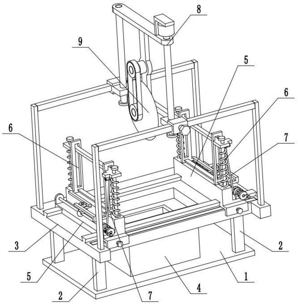
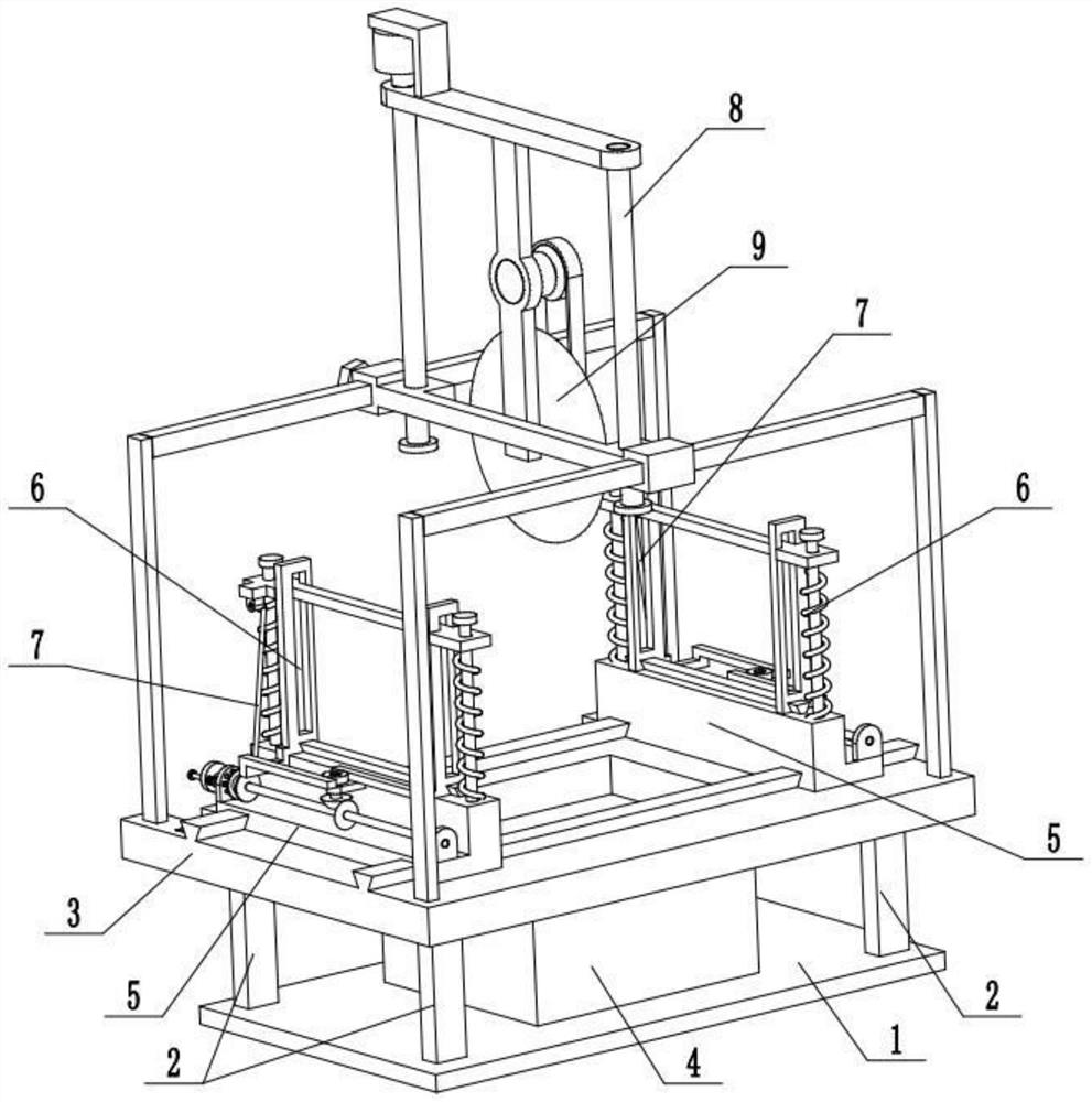
[0025] Combine below Figure 1-7 Description of this embodiment, a wood cutting device for architectural decoration, including a base 1, supporting legs 2, a horizontal working plate 3, a sawdust recovery box 4, a fixing slide 5, a wood fixing assembly 6, a nylon rope 7, a cutting slide Seat 8 and cutting device 9, the four corners of the top surface of the base 1 are respectively fixedly connected to a support leg 2, the horizontal working board 3 is fixedly connected to the four support legs 2, and the sawdust recovery box 4 is placed in the center of the base 1 position, the sawdust recovery box 4 is located below the horizontal working plate 3, two fixing slides 5 are provided, and the two fixing slides 5 are symmetrically slidably connected to the lower end of the horizontal working plate 3, and the two fixing slides 5 are Connect a wood fixing assembly 6 respectively, the front ends of the upper ends of the two wood fixing assemblies 6 are respectively fixedly connected ...

specific Embodiment approach 2

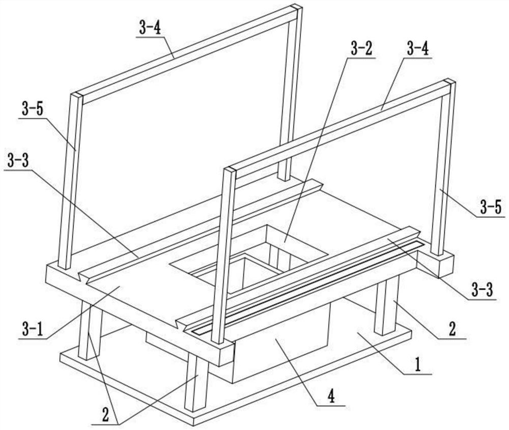
[0027] Combine below Figure 1-7To illustrate this embodiment, the horizontal working board 3 includes a working board body 3-1, a chip removal channel 3-2, a trapezoidal slide rail 3-3, a beam 3-4 and a vertical bar 3-5; the working board body 3 -1 is fixedly connected to the four support legs 2, the center of the working board body 3-1 is provided with a chip removal channel 3-2, the sawdust recovery box 4 is located below the chip removal channel 3-2, and two trapezoidal slide rails 3 -3 is symmetrically fixedly connected to the two ends of the top surface of the working board body 3-1; there are two crossbeams 3-4, and the two ends of the two crossbeams 3-4 are respectively fixedly connected to a vertical bar 3-5; The crossbeam 3-4 is fixedly connected to the outer ends of the front and rear ends of the working plate body 3-1 through the vertical rod 3-5 respectively. The front end of the working board body 3-1 is provided with a scale, which is convenient for measuring t...

specific Embodiment approach 3

[0029] Combine below Figure 1-7 To illustrate the present embodiment, the fixed element sliding seat 5 includes a sliding base 5-1, a screw fixing seat 5-2, a fastening screw 5-3, a support seat 5-4, a trapezoidal sliding bar 5-5, and a rear seat plate 5-6, front seat plate 5-7, rotating shaft 5-8, driving bevel gear 5-9, rope winding wheel 5-10, jack 5-11 and clip 5-12; sliding base 5-1 is slidably connected on On the two trapezoidal slide rails 3-3, the front end of the sliding base 5-1 is fixedly connected to the horizontal plate of the screw mounting base 5-2, and the vertical plate of the screw mounting base 5-2 is threaded to fasten the screw 5-3. The fixed screw 5-3 is pushed against the front end surface of the working plate body 3-1; the inner end of the sliding base 5-1 is fixedly connected to the support seat 5-4, and the middle end of the top surface of the support seat 5-4 is fixedly connected to the trapezoidal slide Rod 5-5; the front seat plate 5-7 and the re...


PUM


Abstract

The invention relates to the field of building material machining equipment, in particular to a wood cutting device for building decorations. Four corners of the top surface of a base are correspondingly and fixedly connected with supporting legs, a horizontal working plate is fixedly connected to the four supporting legs, a wood chip recycling box is placed in the center position of the base, andis located below the horizontal working plate, two fixing piece sliding bases are arranged, and are symmetrically connected to the lower end of the horizontal working plate in a sliding mode, and thetwo fixing piece sliding bases are both connected with wood fixing assemblies. According to the wood cutting device, wood can be fixed, the fixed wood is not easy to shift, so that cutting of the wood is more smooth, and scrapping of the wood and the waste of wood resources is avoided; the device can be adapt to the wood with different sizes, so that the problem that the application range is limited is solved; and wood chips generated during cutting work are collected into the wood chip recycling box, so that inconvenience to constructors is avoided.

Description

technical field [0001] The invention relates to the field of building material processing equipment, in particular to a wood cutting device for building decoration. Background technique [0002] With the development of the modern mechanical processing industry, the requirements for cutting quality and precision are constantly improving, and the requirements for improving production efficiency, reducing production costs, and highly intelligent automatic cutting functions are also increasing. At present, when the wood cutters on the market are in use, the user needs to press the wood with his hands to fix the wood when cutting. When the technology is used, the wood is cut by the saw blade, but when there is no mechanical fixation, the wood is easy to shift, thus causing the scrap of the wood, which seriously wastes the wood resources, and the limiting device in the prior art does not It cannot adapt to wood of different sizes, and the scope of application is relatively limite...

Claims


Application Information

Patent Timeline
Patent Type & Authority Patents(China)
IPC IPC(8): B27C5/02B27C5/06B27G3/00
CPCB27C5/02B27C5/06B27G3/00
Inventor 唐海玉
Owner 安徽盛宁建设工程有限公司
Why Eureka
Try Eureka