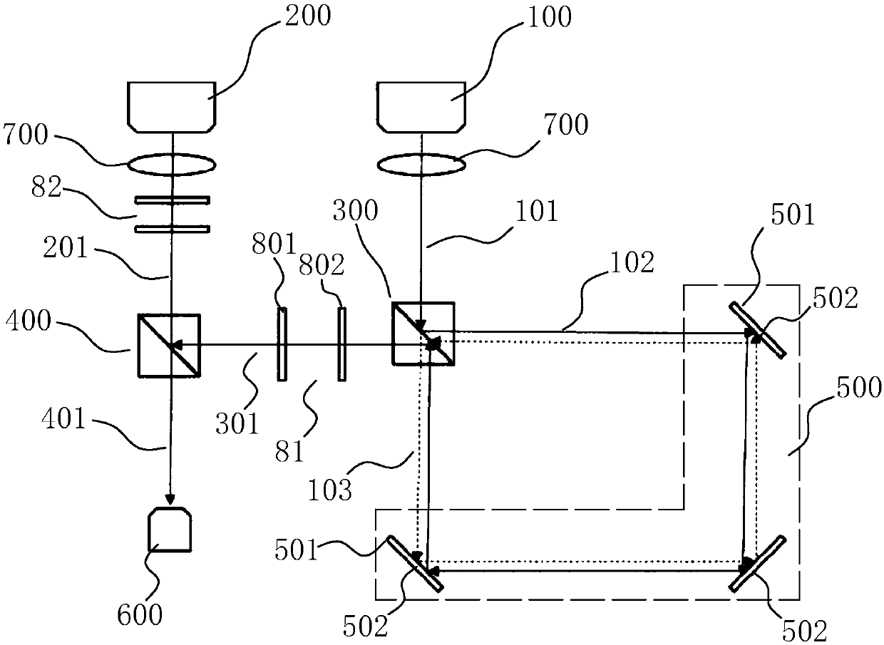
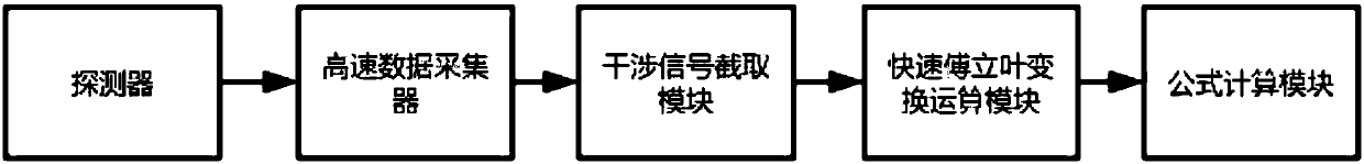
[0066] Preferably, in an embodiment of the present invention, the voltage signal generated by the high-bandwidth detector first passes through a low-pass filter with a bandwidth of half the repetition frequency, and then is collected by a high-speed data collector, which can remove the signal In the non-coherent part, the continuous interference signal 401 is directly obtained, and the sampling period of the high-speed data collector can also be set at will.
[0067] In another embodiment of the present invention, the high-speed data collector directly collects the voltage signal generated by the high-bandwidth detector. At this time, the sampling period of the high-speed data collector is the repetition frequency of the local oscillator optical comb signal 201, and is adjusted by Phase maximizes the sampling signal-to-noise ratio.
[0068] The optical frequency comb signal appears as a femtosecond carrier envelope pulse in the time domain. The signal optical frequency comb is used as the light source of the Sagnac interferometer. When the measurement loop rotates, the first optical comb signal 102 and the second optical comb signal 103 The Sagnac effect occurs on the first beam splitter 300, the optical lengths of the first optical comb signal 102 and the second optical comb signal 103 are changed and have different phase delays. The two beams of light generate two interference signals 401 with different positions. The single pulse of the optical comb signal 301 will be split into double pulses with constant time shift. The amplitudes of these interference signals 401 are approximately the same, but this time shift is very small, and it is difficult to measure accurately using general detection methods, so it needs to be used A local oscillator optical comb signal 201 with a slight repetition frequency difference from the signal optical frequency comb performs multi-heterodyne interference with two sets of measuring optical pulses. If the local oscillator optical pulse signal is used as the external clock to start sampling, the collected point is There is a fixed multiple relationship between the time delay between the local oscillator and the two sets of measured optical pulses, and the time delay between the two sets of cross-correlation functions and the original time delay are respectively fitted to the slope of the Fourier transform phase spectrum The time delay between the two sets of cross-correlation functions can be obtained, that is, by analyzing the interference signal 401 after multi-heterodyne interference with the local oscillator optical comb signal 201, the absolute angular velocity of the rotation of the measurement loop can be obtained.
[0069] A single interference period is a processing period, and an angular velocity calculation is performed in each processing period. The interference signal 401 intercepts the interference signal 401 of the module in each interference period. In one interference period, two obvious interference signals 401 can be intercepted and calculated Record the time difference t corresponding to the two time intervals 0.
[0070] The fast Fourier transform operation module performs fast Fourier transform on the two intercepted interference signals 401, respectively calculates the phase frequency spectrum and then performs subtraction, and then uses the least square method to fit the slope k.
[0071] Since the slope difference of the phase spectrum is equal to the time shift of the signal, the calculated thickness of a single interference periodic signal can be obtained by the following formula through the slope k and the known established time shift:
[0072]
[0073] Among them, c is the speed of light, A is the area enclosed by the measuring circuit, Δf r To measure the repetition frequency difference between the optical comb signal 101 and the local oscillator optical comb signal 201, f s In order to measure the repetition frequency of the optical comb signal 101, Δτ is the precise time difference corresponding to the center of the two interference signals 401 obtained by Fourier transform and least square fitting, namely Δτ=k+t 0.
[0074] Therefore, the above formula can be changed to:
[0075]
[0076] In combination with the first embodiment of the measurement arm optical path 500 of the present invention, the measurement arm optical path 500 includes a plurality of reflectors 502, and the measurement arm optical path 500 is formed between the plurality of reflectors 502. The measuring arm optical path 500 composed of the reflecting mirror 502 has the function of low cost and easy correction.
[0077] In combination with the second embodiment of the measuring arm optical path 500 of the present invention, the measuring arm optical path 500 is an optical fiber ring. Through the optical fiber ring, it is easy to install and stable.
[0078] The first beam splitter 300 and/or the second beam splitter 400 is a beam splitter prism. In combination with the first embodiment of the measuring arm optical path 500, the mirrors 502 at both ends of the measuring arm optical path 500 serve as ports 501 respectively corresponding to the reflection side and the transmission side of the beam splitter prism. In combination with the first embodiment of the optical path 500 of the measuring arm, the two ports 501 of the fiber ring respectively correspond to the reflection side and the transmission side of the beam splitter prism.
[0079] A parallel light shaper 700 is provided between the signal optical frequency comb transmitter 100 and the first optical splitter 300 and/or between the local oscillator optical frequency comb transmitter 200 and the second optical splitter 400. The parallel light shaper 700 is a convex lens.
[0080] A first polarization module 81 for processing the combined optical comb signal 301 into a polarization state is arranged between the first optical splitter 300 and the second optical splitter 400, a local oscillator optical frequency comb transmitter 200 and a second optical splitter A second polarization module 82 for processing the emitted local vibration comb signal 201 into a polarization state is arranged between 400.
[0081] The first polarization module 81 and the second polarization module include an S polarizer 801 and a wave plate 802 that convert the combined optical comb signal 301 and the emitted local oscillator optical comb signal 201 into S linearly polarized light. The local oscillator optical comb signal 201, combined The optical comb signal 301 is output through the wave plate 802 and the S polarizer 801 in sequence, and the combination of the wave plate 802 and the S polarizer 801 can improve the signal-to-noise ratio of the entire optical path system.
[0082] A narrow-band filter is arranged between the second optical splitter 400 and the measuring device 600, and the interference signal 401 is received by a high-bandwidth detector after passing through a narrow-band filter. The use of the filter can ensure the multiple optical frequency combs. No spectrum aliasing occurs in heterodyne interference.
[0083] Preferably, a filter with adjustable center wavelength and bandwidth is used. When optimizing the center wavelength and bandwidth, the time-domain waveform and spectral position of the detector signal should be used. The time-domain interference part has enough points and the spectral center is at the repetition frequency of the optical frequency comb. When the position is one-quarter of, the signal aliasing reaches the minimum, and the dual optical frequency comb measuring angular velocity system can reach the maximum accuracy.
[0084] When adjusting the interference optical path, the following steps need to be followed: put an optical power meter between the quarter wave plate and the S polarizer 801, rotate the S polarizer 801 corresponding to the signal optical frequency comb until the optical power is maximized, and then rotate the signal light The half-wave plate corresponding to the frequency comb until the maximum optical power. Then, the optical power meter is moved between the second beam splitter 400 and the optical filter to cover the local oscillator optical frequency comb emitter 200, and the optical power at this time is recorded. Turn on the local oscillator optical frequency comb emitter 200, cover the signal optical frequency comb emitter 100, adjust the S polarizer 801 corresponding to the local oscillator optical frequency comb emitter 200 until the optical power is the maximum, and then rotate the local oscillator optical frequency comb emitter 200 The corresponding half-wave plate makes the optical power equal to the previously recorded optical power. At this time, the signal-to-noise ratio of the entire system is optimized to the maximum after the signal light is turned on.
[0085] Reference image 3 , Figure 4 As shown, an embodiment of the present invention provides an angular velocity measurement method, including the following steps:
[0086] Transmit the measurement optical comb signal 101 and the local oscillator optical comb signal 201;
[0087] The measuring optical comb signal 101 is divided into a first optical comb signal 102 and a second optical comb signal 103 by the first optical splitter 300;
[0088] The first optical comb signal 102 and the second optical comb signal 103 are transmitted in opposite directions in the measurement loop, and combined light on the first optical splitter 300 to form a combined optical comb signal 301;
[0089] The second optical splitter 400 receives the local oscillator optical comb signal 201 from the local oscillator optical frequency comb transmitter 200 and the combined optical comb signal 301 from the first optical splitter 300. The local oscillator optical comb signal 201 and the combined optical comb signal 301 are in Multiple heterodyne interference occurs on the second beam splitter 400 and an interference signal 401 is output;
[0090] The interference signal 401 is obtained and the absolute angular velocity is calculated.
[0091] Further, the calculation method of the absolute angular velocity includes:
[0092] Intercept two successive interference signals 401 in an interference cycle, and calculate the precise time difference Δτ corresponding to the centers of the two interference signals 401,
[0093] The absolute angular velocity Ω calculated by a single interference periodic signal is obtained by the following formula,
[0094]
[0095] Among them, c is the speed of light, A is the area enclosed by the measuring circuit, Δf r To measure the repetition frequency difference between the optical comb signal 101 and the local oscillator optical comb signal 201, f s To measure the repetition frequency of the optical comb signal 101, Δτ is the precise time difference corresponding to the center of the two interference signals 401 obtained by Fourier transform and least square fitting.
[0096] Further, the precise time difference Δτ is calculated through the following steps:
[0097] Obtain the time difference t corresponding to the two time intervals of the two interference signals 401 intercepted in one interference period 0;
[0098] Fast Fourier transform is performed on the two interfering signals 401 that are cut out, and the phase frequency spectrum is obtained respectively and then subtracted, and then the slope k is fitted by the least square method;
[0099] The precise time difference corresponding to the center of the two interference signals 401 Δτ=k+t 0.
[0100] An embodiment of the present invention provides a vehicle that uses the angular velocity measurement device 600 in the above-mentioned embodiment of the present invention.
[0101] The vehicle may be a vehicle of sea, land, or air, such as an aircraft, a ship, a cruise ship, a vehicle, and the like.
[0102] According to the angular velocity measuring device 600, the method and the carrier provided by the above-mentioned embodiments of the present invention, the optical comb signal is measured by the measurement optical comb signal 101 and the local oscillator optical comb signal 201 with repetition frequency difference and overlapping spectral range. 101 is divided into the first optical comb signal 102 and the second optical comb signal 103 transmitted in opposite directions in the measurement circuit by the first beam splitter 300, and then the combined optical comb signal 301 is output on the first beam splitter 300. The comb signal 301 and the local oscillator optical comb signal 201 have multiple heterodyne interference and output an interference signal 401. When the measurement loop rotates, the first optical comb signal 102 and the second optical comb signal 103 are on the first beam splitter 300 When the Sagnac effect occurs, the optical lengths of the first optical comb signal 102 and the second optical comb signal 103 change and have different phase delays. The single pulse of the combined optical comb signal 301 will be split into double pulses with constant time shift. After performing multi-heterodyne interference with the local oscillator optical comb signal 201, the interference signal 401 is analyzed to obtain the absolute angular velocity of the rotation of the measurement circuit. The above-mentioned embodiment of the present invention only needs to use a single point detector to accurately and quickly measure Absolute angular velocity.