Intelligent monitoring equipment for monitoring fault of video camera

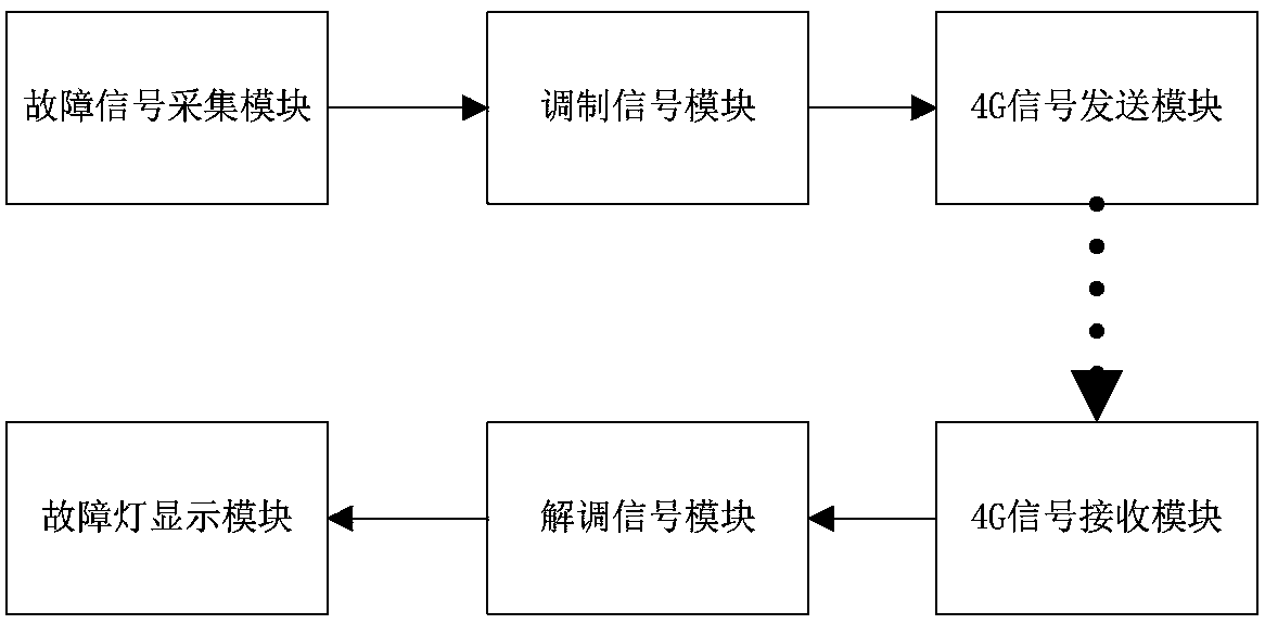
A surveillance camera, intelligent analysis technology, applied in image communication, TV, electrical components, etc., can solve problems such as signal imbalance, 4G signal receiving module signal distortion, frequency instability, etc.

Active Publication Date: 2019-04-02
河南亿秒电子科技有限公司
View PDF5 Cites 12 Cited by
  • Summary
  • Abstract
  • Description
  • Claims
  • Application Information

AI Technical Summary

Problems solved by technology

[0004] In addition, in the actual application of this kind of equipment, when the signal output by the modulating signal module passes through the 4G signal...

Method used


Image

  • Intelligent monitoring equipment for monitoring fault of video camera
  • Intelligent monitoring equipment for monitoring fault of video camera
  • Intelligent monitoring equipment for monitoring fault of video camera

Examples


Embodiment 1

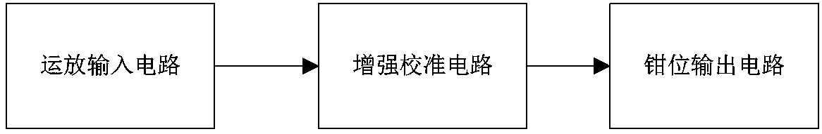
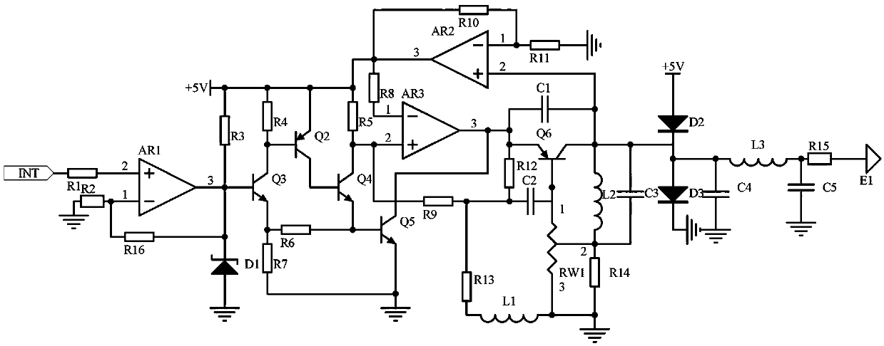
[0015] Embodiment 1, an intelligent analysis device for monitoring camera faults, including an operational amplifier input circuit, an enhanced calibration circuit, and a clamp output circuit, and the operational amplifier input circuit receives the output of the modulating signal module in the intelligent analysis device for monitoring camera faults The data signal is input into the enhanced calibration circuit after using the operational amplifier AR1 to amplify the signal in phase. The enhanced calibration circuit uses the triode Q2-transistor Q5 to form a signal enhancement circuit to enhance the signal, and simultaneously uses the operational amplifier AR3 and the triode Q6. RW1 forms a frequency modulation circuit to modulate the signal frequency, and designed the operational amplifier AR2 to feed back the signal to the emitter of the transistor Q2 to adjust the output signal potential of the frequency modulation circuit. Finally, the clamp output circuit uses diode D2 and...

Embodiment 2

[0018] Embodiment 2, on the basis of Embodiment 1, the clamp output circuit uses diode D2 and diode D3 to clamp the output signal of the enhanced calibration circuit within 0~+5V, and at the same time, it is composed of inductance L3, capacitor C4, and capacitor C5 The π-type filter circuit filters the output, which improves the anti-interference of the signal, that is, the input signal transmitter E1, the signal transmitter E1 is also used for the 4G signal transmission module in the intelligent analysis equipment for monitoring camera faults, and the diode D2 The negative pole is connected to the positive pole of the diode D3, the collector of the transistor Q6, one end of the inductor L3, and one end of the capacitor C4, the positive pole of the diode D2 is connected to the power supply +5V, the negative pole of the diode D3 is grounded, the other end of the capacitor C4 is grounded, and the other end of the inductor L3 One end of the resistor R15 and one end of the capacito...


PUM


Abstract

The invention discloses intelligent monitoring equipment for monitoring a fault of a video camera. The intelligent monitoring equipment comprises an operational amplifier input circuit, an enhanced calibration circuit and a clamp output circuit, wherein the operational amplifier input circuit receives a data signal output by a modulation signal module in the intelligent monitoring equipment for monitoring the fault of the video camera; the enhanced calibration circuit utilizes a triode Q2, a triode Q3, a triode Q4 and a triode Q5 to form a signal enhancement circuit for enhancing signals; an operational amplifier AR3 and a variable resistor RW1 form a frequency modulation circuit for modulating frequency of signals; an operational amplifier AR2 is designed for feeding back signals to an emitter of the triode Q2, so as to adjust output signal potential of the frequency modulation circuit; and finally, the clamp output circuit utilizes a diode D2 and a diode D3 to clamp an output signalof the enhanced calibration circuit to be in a range from 0 to +5 V, and the signal is filtered for output by means of a pi type filtering circuit composed of an inductor L3, a capacitor C4 and a capacitor C5. The intelligent monitoring equipment realizes automatic calibration of the signals, stabilizes the signal frequency and potential, and prevents signal distortion.

Description

technical field [0001] The invention relates to the technical field of signal collection and calibration, in particular to an intelligent analysis device for monitoring camera faults. Background technique [0002] With the rapid development of video network technology, video surveillance is widely used in many fields such as safe construction, environmental monitoring, enterprise operation and production, and residents' life. At the same time, the fault diagnosis and elimination of monitoring equipment and network has also become a new topic at present. The invention is a set of monitoring equipment and a network fault intelligent analysis system. Including fault signal acquisition module, modulation signal module, 4G signal transmission module and 4G signal reception module, demodulation signal module and remote monitoring camera fault intelligent analysis system. The fault signal acquisition module uses the optical sensor to collect the optical signal changes of the moni...

Claims


Application Information

Patent Timeline
IPC IPC(8): H04N17/00H03F1/02H03F1/26H03F1/32
CPCH03F1/0205H03F1/26H03F1/32H04N17/002
Inventor 张宏排
Owner 河南亿秒电子科技有限公司
Why Eureka
Try Eureka