moving radial bed reactor

A reactor and radial bed technology, applied in the field of reactors, can solve problems such as uneven distribution, catalyst feed blockage, etc.

Active Publication Date: 2021-09-10
SINOPEC ENG +1
View PDF6 Cites 0 Cited by
  • Summary
  • Abstract
  • Description
  • Claims
  • Application Information

AI Technical Summary

Problems solved by technology

[0006] The purpose of this disclosure is to provide a moving radial bed reactor that solves the problems of catalyst feed clogging and uneven distribution in existing reactors

Method used


Image

  • moving radial bed reactor
  • moving radial bed reactor
  • moving radial bed reactor

Examples


Embodiment 1

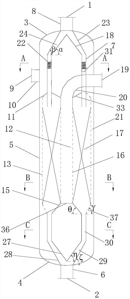
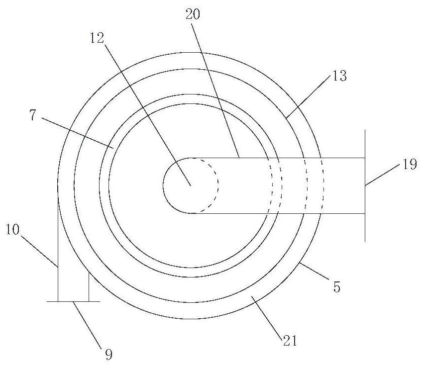
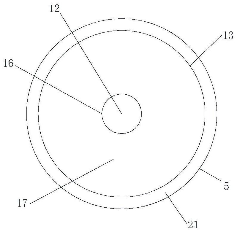
[0086] Such as figure 1 , figure 2 , image 3 , Figure 5 , Image 6 As shown, the reactor used in this embodiment is provided with a catalyst inlet 1 at the top, a catalyst outlet 2 at the bottom, a radial catalytic reaction unit 17, a central tube 12, and a feeder for tangentially feeding the upper part of the shell. Port 9, discharge port 19. The inner diameter of the reactor in this embodiment is 3100mm, the tangent length of the shell is 21500mm, the length of the central tube is 14000mm, the inner diameter of the central tube is 1150mm, the thickness of the catalytic reaction unit is 825mm, the annular gap is 150mm, and the inner diameter of the gas outlet elbow 20 is 900mm. The distance from the apex of the catalyst deflector 31 to the centerline of the gas outlet elbow 20 is 2000 mm, and the inner diameter of the first hollow interlayer cylindrical tube 7 is 2150 mm. The inclination angles of the inner ring plate, the outer ring plate and the horizontal plane are...

Embodiment 2

[0089] Such as figure 1 , figure 2 , Figure 4 , Figure 5 , Image 6 As shown, the reactor used in this embodiment is the same as the reactor used in Example 1 in terms of reactor size, catalyst inlet and outlet system, and raw material inlet and outlet system. The area surrounded by the body is formed, and the catalytic reaction unit is formed by the area between the Johnson net and the central tube to accommodate the passage of the catalyst.

[0090] The reactor of this embodiment is also applied to the continuous reforming process, and the catalyst is a bimetallic Pt-Sn spherical catalyst with a diameter of 2.5-2.8 mm. Reaction raw material is identical with embodiment 1, and reaction pressure is 0.2~1.0MPaG, and the temperature of reaction is 430~550 ℃, and weight hourly space velocity (WHSV) is 0.8~3.0h -1 . The pressure drop of the reactor is less than 10kPa, and the axial temperature difference of the catalytic reaction unit is less than 2°C, which shows that th...

Embodiment 3

[0092] Such as figure 1 , figure 2 , Figure 4 , Figure 5 , Image 6 As shown, the reactor used in this example is the same as the reactor used in Example 2 in terms of reactor size, catalyst inlet and outlet system, raw material inlet and outlet system, annulus and other parameters. The difference is that the reactor is used for methanol to olefins process.

[0093] In this example, the catalyst used for methanol-to-olefins is spherical SAPO-34, the particle diameter of which is 2.1-2.5 mm, and the reaction raw material is H 2 O, CH 3 OH, CH 3 OCH 3 The formed mixture has a reaction pressure of 0.05-0.3MPa and a volumetric space velocity (GHSV) of 0.5-3.2h -1 , The reaction temperature is 405-510°C. The pressure drop of the reactor is less than 20kPa, and the axial temperature difference of the catalytic reaction unit is less than 3.5°C, which shows that the reaction raw materials are evenly distributed in the axial direction, and there is no "cavity" and "sticking"...


PUM


Abstract

The disclosure relates to a moving radial bed reactor, a catalyst feed distributor is provided between the catalyst inlet and the catalytic reaction unit of the reactor, the feed distributor communicates with the catalyst inlet and the catalytic reaction unit, and has a The annular flow cross-section compatible with the catalytic reaction unit can realize the automatic and uniform feeding of the catalyst. The catalyst is set up to enter and exit from the bottom, making full use of its own gravity. The problem of short circuit of reaction raw materials caused by uneven materials. The reactants can flow from outside to inside or from inside to outside in the catalytic reaction unit, and the reactants can move relative or in the same direction in the annulus and the central tube, and the bed pressure drop is small.

Description

technical field [0001] The present disclosure relates to the field of reactors, in particular, to a moving radial bed reactor. Background technique [0002] Moving bed reactors are widely used in petrochemical, coal chemical and environmental protection fields, especially in continuous reforming, coal gasification, methanol to olefins (MTO), methanol to aromatics (MTA), toluene disproportionation and other processes Mature. The biggest feature of the moving bed reactor is that the catalyst can move in and out of the reactor continuously, but the moving speed is lower than that of the catalyst in the fluidized bed reactor. From a macro point of view, the operating performance of the moving bed reactor is between that of the fixed bed reactor and the fluidized bed reactor. Therefore, the moving bed reactor is especially suitable for the occasions where the catalyst deactivation rate is medium, such as the catalyst deactivation time is several minutes to hundreds of minutes, ...

Claims


Application Information

Patent Timeline
Patent Type & Authority Patents(China)
IPC IPC(8): B01J8/18
CPCB01J8/1881
Inventor 张旭戴文松周桂娟智凯敏
Owner SINOPEC ENG
Why Eureka
Try Eureka