A kind of preparation method of micro tool electrode

A tool electrode and electrode technology, which is applied in the field of preparation of micro tool electrodes, can solve the problems of low processing efficiency and insignificant improvement of processing efficiency, and achieve the effects of improving the corrosion rate, increasing the electrolysis reaction area, and improving the preparation efficiency.

Active Publication Date: 2020-07-31
JIANGXI UNIV OF SCI & TECH
View PDF7 Cites 0 Cited by
  • Summary
  • Abstract
  • Description
  • Claims
  • Application Information

AI Technical Summary

Problems solved by technology

However, this technology is mainly based on grinding wheel grinding to remove workpiece material, supplemented by electrolytic machining to assist material removal, the processing efficiency is low, and its processing efficiency is not significantly improved compared with traditional grinding.

Method used


Image

  • A kind of preparation method of micro tool electrode
  • A kind of preparation method of micro tool electrode
  • A kind of preparation method of micro tool electrode

Examples


Embodiment 1

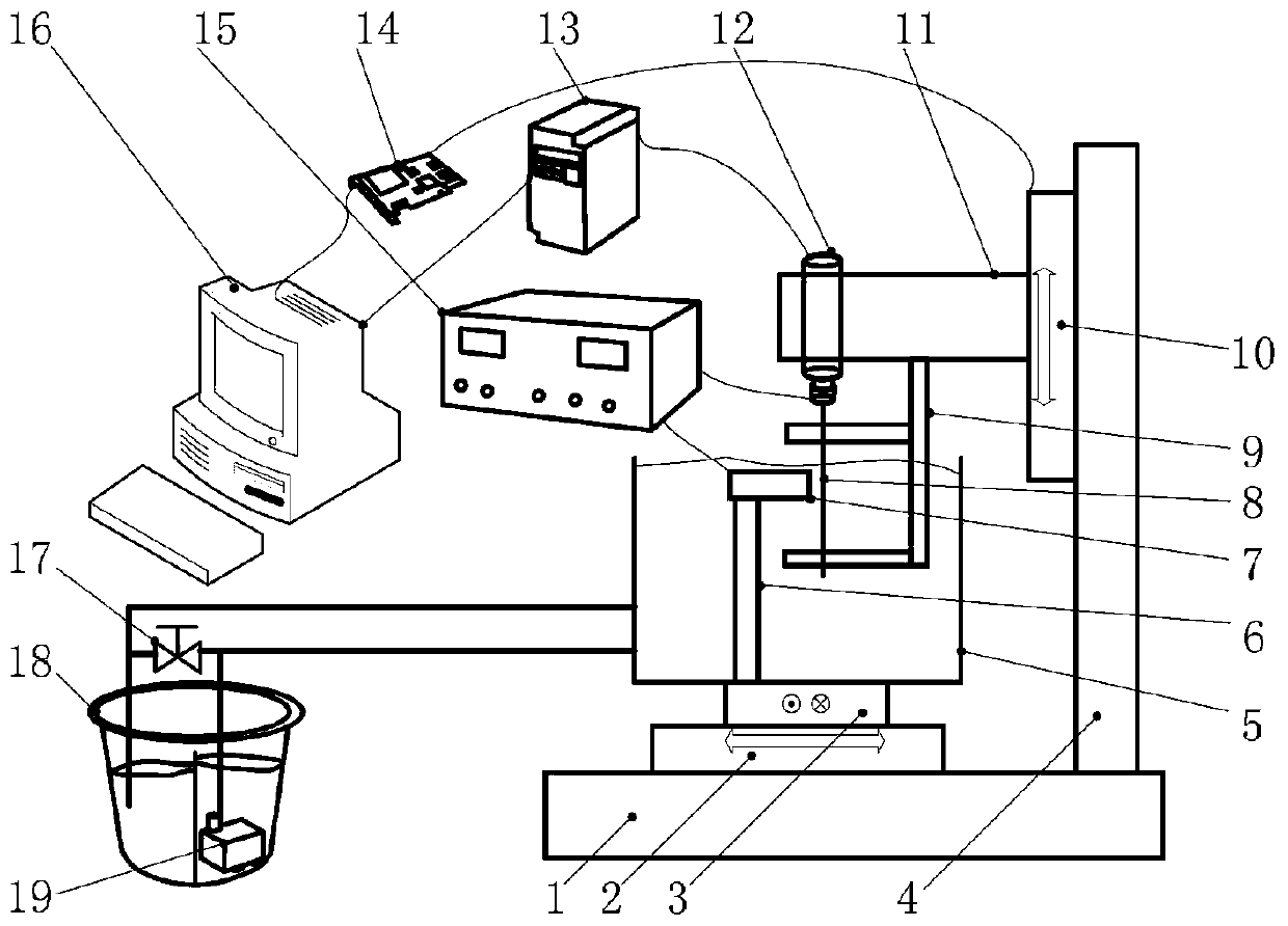
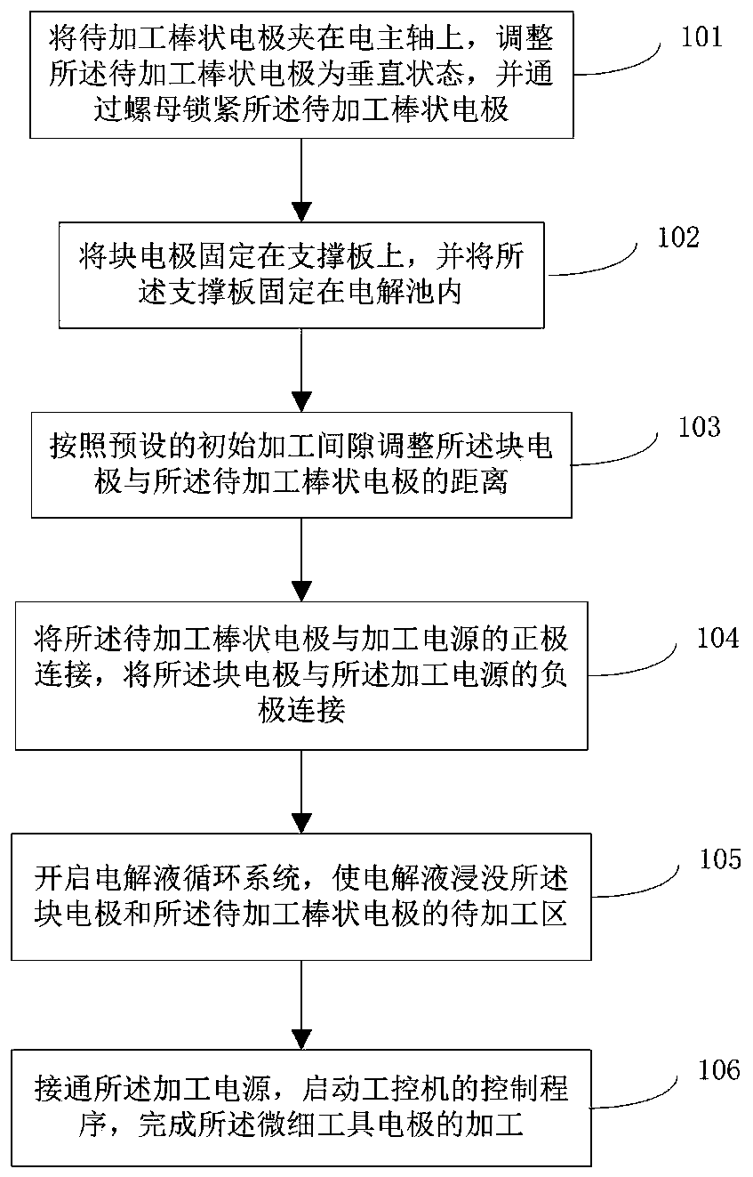
[0052] Such as figure 1 As shown, the preparation device for the micro-tool electrode provided in this embodiment includes: a base platform 1 and a column 4 vertically fixed on one end of the base platform 1; Shaft 10, one end of connecting rod 11 is fixed at the middle position of motion shaft 10, the other end of connecting rod 11 is installed electric spindle 12, the lower surface of connecting rod 11 is fixed fixture 9, fixture 9 has two upper and lower arms, electric spindle 12 And the clamp 9 is used to fix the rod-shaped electrode 8 to be processed; the motion shaft 2 that drives the block electrode 7 along the linear direction perpendicular to the central axis of the electric spindle 12 is set on the base platform 1, above the motion shaft 2 The motion shaft 3 is set, the motion direction of the motion shaft 3 is perpendicular to the direction of the feed motion, the upper surface of the motion shaft 3 fixes the electrolytic cell 5, the block electrode 7 is fixed on th...

Embodiment 2

[0083] Such as Figure 4 as shown, Figure 4 (a) is a three-dimensional schematic diagram of the processed rod electrode, Figure 4 (b) is a schematic plan view of the processed rod electrode, Figure 4 (c) is a cross-sectional view of the processed rod electrode.

[0084] The control program of machining edge-cutting electrode 24 comprises:

[0085] Adjusting the distance between the block electrode 7 and the rod-shaped electrode 8 to be processed according to the preset initial processing gap;

[0086] Control the rod-shaped electrode 8 to be processed to reciprocate up and down in the vertical direction;

[0087] The block electrode 7 is controlled to perform a feed motion along a straight line perpendicular to the central axis of the electric spindle 12 .

[0088] According to the control program, a certain width is electrolytically cut on the rod-shaped electrode 8 to be processed, and the processing of a finely edge-cut electrode 23 is completed.

Embodiment 3

[0090] Figure 5 For the schematic diagram of the process of electrolytically preparing the probe electrode, the control program for processing the probe electrode 21 and the probe electrode 22 includes:

[0091] Adjusting the distance between the block electrode 7 and the rod-shaped electrode 8 to be processed according to the preset initial processing gap;

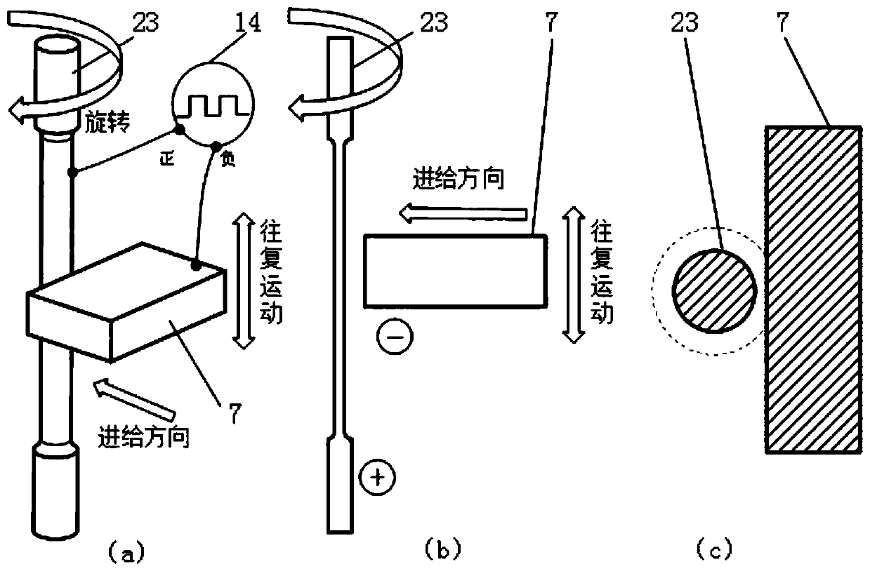
[0092] Control the rod-shaped electrode 8 to be processed to perform up-and-down reciprocating motion along the vertical direction and rotational motion centered on the central axis of the electric spindle 12 at the same time, such as Image 6 As shown in (b), the speed curve of the rod-shaped electrode 8 to be processed reciprocating up and down is a sinusoidal curve;

[0093] The block electrode 7 is controlled to perform a feed motion along a straight line perpendicular to the central axis of the electric spindle 12 .

[0094] Because the speed of the rod-shaped electrode 8 to be processed is very slow at the upper ...


PUM


Abstract

The invention discloses a preparation method of fine tool electrodes. The fine tool electrodes of different shapes are prepared by adjusting relative movement of a block electrode and a to-be-processrodlike electrode according to an electrochemical anodic dissolution principle by taking the to-be-process rodlike electrode as an anode and the block electrode as a cathode. An electrolyte immerses the block electrode and a to-be-processed area of the to-be-process rodlike electrode to achieve full electrochemical machining. By taking the block electrode of certain thickness of the cathode, the electrolytic reaction area is increased, so that the etch rate of the anode is improved favorably and the preparation efficiency of the fine tool electrodes is improved.

Description

technical field [0001] The invention relates to the field of electrolytic machining, in particular to a preparation method of a micro tool electrode. Background technique [0002] Due to the advantages of small size, light weight, and low energy consumption, miniaturized products have a major impact on the development of instrumentation, bioengineering, and medical treatment, and have become one of the hot research issues. Micromachining is a supporting technology for product miniaturization, and microtools are one of the necessary conditions for realizing micromachining, which directly affects the processing accuracy, minimum processing size and processing stability of micromachining. [0003] Electrolytic grinding compound machining is a kind of electric discharge compound machining method that has been widely used in recent years. This technology is to increase the power supply of electrolytic machining on the basis of traditional grinding machine tools. Electrolyte, so ...

Claims


Application Information

Patent Timeline
Patent Type & Authority Patents(China)
IPC IPC(8): B23H5/08B23H5/10
CPCB23H5/08B23H5/10
Inventor 邹祥和
Owner JIANGXI UNIV OF SCI & TECH
Why Eureka
Try Eureka