Reverse osmosis recycling device of electrophoresis phosphating wastewater

A recovery device and reverse osmosis technology, which is applied in the field of phosphating process, can solve the problems of affecting the conductivity of workpieces, large water consumption, and affecting conductivity, and achieve high-quality film-forming quality, high film-forming speed, and quality assurance.

Pending Publication Date: 2019-04-05
襄阳市志达海成科技实业有限公司
View PDF6 Cites 0 Cited by
  • Summary
  • Abstract
  • Description
  • Claims
  • Application Information

AI Technical Summary

Problems solved by technology

The phosphating water washing process is two times of dipping and spraying. This process is prone to unclean cleaning of the surface and inner cavity of the workpiece, which will affect the conductivity and pollute the electrophoretic bath, which will affect the quality of the electrophoretic coating and the electrophoretic bath. stability
The conventional phosphating cleaning tank is designed as an independent tank. The water in the tank needs to be discharged directly after being polluted by impurities such as phosphating solution and phosphating slag, which consumes a lot of water and increases the treatment cost of phosphating sewage.
[0003] Disadvantages of the existing technology: the existing phosphating water washing process does not clean the workpiece cleanly, affects the conductivity of the workpiece, and is easy to pollute the electrophoresis bath, which directly affects the quality of the electrophoretic coating

Method used


Image

  • Reverse osmosis recycling device of electrophoresis phosphating wastewater
  • Reverse osmosis recycling device of electrophoresis phosphating wastewater

Examples


Embodiment Construction

[0018] The following will clearly and completely describe the technical solutions in the embodiments of the present invention with reference to the accompanying drawings in the embodiments of the present invention. Obviously, the described embodiments are only some, not all, embodiments of the present invention.

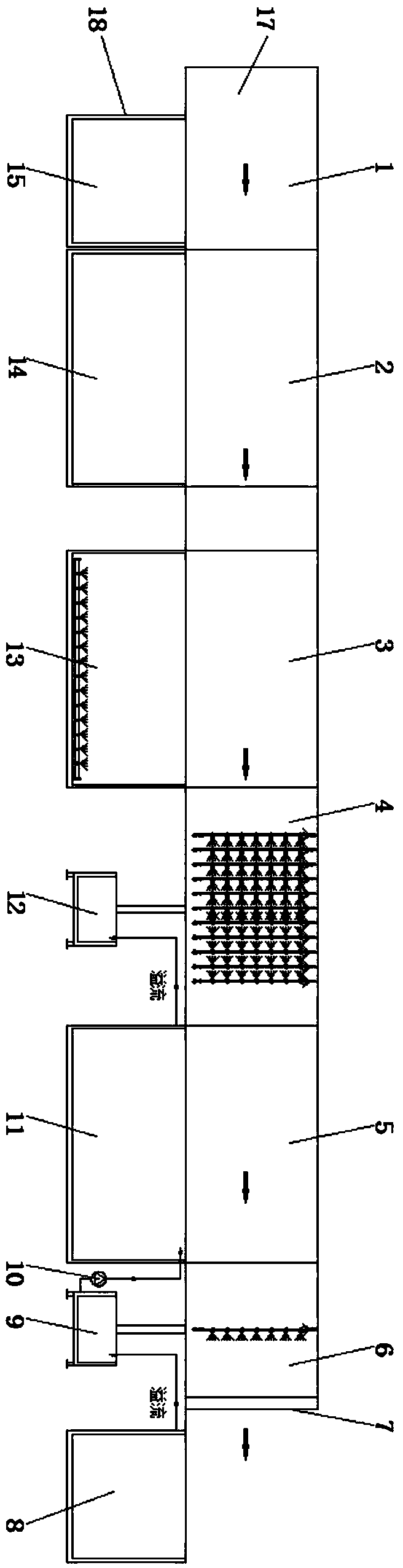
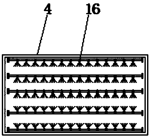
[0019] refer to Figure 1-2 , a reverse osmosis recovery device for electrophoretic phosphating wastewater, including a pipeline area 17 and a treatment area 18, the pipeline area 17 includes a first invasion pool 1, a second invasion pool 2, a third invasion pool 3, and a first phosphating water washing pool 4 , the fourth invasion pool 5, pure water prewashing pool 6 and shed body workpiece outlet 7, the treatment area 18 includes pure water washing invasion pool 8, the second phosphating washing pool 11, phosphating pool 13, surface adjustment pool 14 and degreasing water washing Pool 15, the first invasion pool 1, the second invasion pool 2, the third invasion po...


PUM


Abstract

The invention discloses a reverse osmosis recycling device of electrophoresis phosphating wastewater. The reverse osmosis recycling device of the electrophoresis phosphating wastewater comprises an assembly line area and a processing area, wherein the assembly line area includes a first soaking pool, a second soaking pool, a third soaking pool, a first phosphating water washing pool, a fourth soaking pool, a pure water prewash pool and a shack body workpiece outlet; the processing area includes a pure water washing and soaking pool, a second phosphating water washing pool, a phosphating pool,a meter adjusting pool and a degreasing washing pool; the first soaking pool, the second soaking pool, the third soaking pool and the fourth soaking pool are in through connection, and the first phosphating water washing pool is positioned between the third soaking pool and the fourth soaking pool; and the fourth soaking pool is arranged between the first phosphating water washing pool and the pure water prewash pool. According to the reverse osmosis recycling device of the electrophoresis phosphating wastewater, a cleaning tank communicates with a pipeline, and a circulating water pump is added to make clear water flow at a plurality of stations for multiple use, the water consumption is reduced, and the cleaning process of soaking, spraying, soaking and spraying is used, the extremely low water consumption is realized, and meanwhile, the cleaning effect of a workpiece is controlled, and the quality of electrophoretic coating of the workpiece and the stability of electrophoretic bathare guaranteed.

Description

technical field [0001] The invention relates to the technical field of phosphating process, in particular to a reverse osmosis recovery device for electrophoretic phosphating wastewater. Background technique [0002] Phosphating is a very important process in the pre-treatment of coating. The main purpose is to form a phosphating film and make the coated product more corrosion-resistant. The phosphating water washing process is two washings of dipping and spraying. This process is prone to unclean cleaning of the surface and inner cavity of the workpiece, which will affect the conductivity and pollute the electrophoretic bath, affecting the quality of the electrophoretic coating and the quality of the electrophoretic bath. stability. The conventional phosphating cleaning tank is designed as an independent tank. The water in the tank needs to be discharged directly after being polluted by impurities such as phosphating solution and phosphating slag, which consumes a lot of w...

Claims


Application Information

Patent Timeline
Patent Type & Authority Applications(China)
IPC IPC(8): C25D13/24C25D13/20
CPCC25D13/20C25D13/24
Inventor 杨波
Owner 襄阳市志达海成科技实业有限公司
Why Eureka
Try Eureka