Heat pump unit with solar energy-air source direct expansion evaporator
A heat pump unit and evaporator technology, which is applied in the direction of evaporator/condenser, heat pump, refrigerator, etc., can solve the problems of performance affected by irradiation conditions, low operation efficiency, poor heat exchange performance, etc. The effect of reducing heat exchange equipment and improving stability
- Summary
- Abstract
- Description
- Claims
- Application Information
AI Technical Summary
Problems solved by technology
Method used
Image
Examples
Embodiment 1
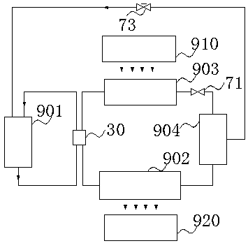
[0040] Such as figure 1 Shown is an embodiment of a heat pump unit of the present invention, the heat pump circulation pipeline of the heat pump unit includes a first pipeline 901 provided with a compressor, a second pipeline 902 provided with a condenser, and a third pipeline provided with an evaporator The pipeline 903 and the fourth pipeline 904 provided with an economizer, wherein the compressor in the first pipeline 901 is a direct-current frequency conversion air supplement enthalpy compressor with an additional suction port, the outlet of the first pipeline 901 and The inlet is respectively connected to one end of the second pipeline 902 and the third pipeline 903 through the four-way reversing valve 30, and a fourth pipeline is connected in series between the other end of the second pipeline 902 and the other end of the third pipeline 903 904 and the two-way decompression valve 71 , the air return port of the economizer in the fourth pipeline 904 is connected with the ...
Embodiment 2
[0045] Such as Figure 7 , Figure 8 , Figure 9 As shown, this embodiment is a heat pump unit with a solar-air source direct expansion evaporator, the difference from Embodiment 1 is that it has a user circulation pipeline 905, and the user circulation pipeline 905 is filled with water as the second working The condenser 40 in the second circulation line 902 exchanges heat energy with the first working medium in the heat pump circulation line. In this embodiment, the condenser 40 is specifically a water-side heat exchanger; the compression in the first line 901 The machine 10 is specifically a DC frequency conversion double-rotor gas supplement and enthalpy increasing compressor, which has a suction port, an additional suction port and an exhaust port; the first pipeline 901 also includes a gas-liquid separator 20, and the gas-liquid separator 20 The gas outlet is connected to the suction port of the compressor 10, the exhaust port of the compressor 10 is connected to the c...
Embodiment 3
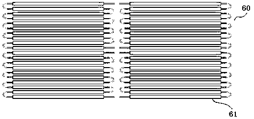
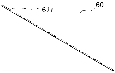
[0051] Embodiment 3 is a heat pump unit. The difference between Embodiment 3 and Embodiment 1 and Embodiment 2 is that a star-shaped fin evaporating tube 61 with internal tooth pattern is used, as Figure 10As shown, the inner tube wall of the evaporator tube 61 is completely covered by the tooth pattern composed of the elongated convex tooth portion 613 and the groove portion 614. The tooth pattern spirals around the central axis of the evaporation tube 61 and is rotationally symmetrical. The helix angle of the tooth pattern is greater than 30° At the same time, the fins 611 of the evaporating tube 61 are also arranged in a symmetrical star shape around the central axis of the evaporating tube 61; wherein, the outer diameter of the evaporating tube is 17mm, and the inner diameter is 12mm; The height difference is zero; the fin 611 is 1.63mm thick, 30mm wide, and the length is equal to the evaporation tube 61; the drawing groove on the fin 611 is 0.25mm deep, the bottom chamfer...
PUM
 Abstract
Description
Claims
Application Information
 - R&D
- Intellectual Property
- Life Sciences
- Materials
- Tech Scout
- Unparalleled Data Quality
- Higher Quality Content
- 60% Fewer Hallucinations
Browse by: Latest US Patents, China's latest patents, Technical Efficacy Thesaurus, Application Domain, Technology Topic, Popular Technical Reports.
© 2025 PatSnap. All rights reserved.Legal|Privacy policy|Modern Slavery Act Transparency Statement|Sitemap|About US| Contact US: help@patsnap.com


