Earth-continuity tester calibration system

A resistance tester and grounding conduction technology, which is applied in the direction of instruments, measuring devices, and measuring electrical variables, etc., can solve the problems of wrong measurement values ​​and poor stability of resistance values, and achieve the effects of strong versatility, high precision and reliability

Pending Publication Date: 2019-04-05
HENAN PROVINCE INST OF METROLOGY
View PDF0 Cites 2 Cited by
  • Summary
  • Abstract
  • Description
  • Claims
  • Application Information

AI Technical Summary

Problems solved by technology

But this kind of standard device has obvious disadvantages. First, it must be verified by four-terminal connection method.
2. Due to the influence of zero point drift, gain drift, nonlinearity, etc., the stability of resistance is poor
3. Due to the limitations of the principle, not all ground resistance testers can be verified. When some ground resistance testers use analog resistance to measure, the measured value is completely wrong.
Ground bond testers with four terminals can be calibrated using the four-terminal method, while ground bond testers with only two terminals can be calibrated using the four-terminal method of simulating resistors unable to calibrate it

Method used


Image

  • Earth-continuity tester calibration system
  • Earth-continuity tester calibration system
  • Earth-continuity tester calibration system

Examples


Embodiment 1

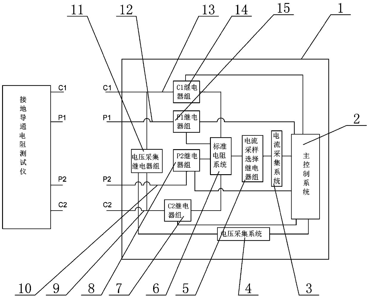
[0045] Such as figure 1 As shown, a calibration system for a ground bond resistance tester includes a housing 1, four terminals and a standard resistance system 6 arranged in the housing 1, a current acquisition system 3, a voltage acquisition system 4, a C1 relay group 14, and a C2 Relay group 7, P1 relay group 15, P2 relay group 8, voltage acquisition relay group 11, current sampling selection relay group 5 and main control system 2, the shell 1 is provided with four terminals, which are respectively C1 terminals , C2 terminal, P1 terminal and P2 terminal, the standard resistance system 6 is electrically connected to the C1 bus 13 through the C1 relay group 14, the C1 bus 13 is connected to the C1 terminal on the shell 1, and the standard resistance system 6 is connected to the C2 relay group 7 Electrically connected with C2 bus 9, C2 bus 9 is connected with C2 terminal on shell 1, standard resistance system 6 is electrically connected with P1 bus 12 through P1 relay group 1...

Embodiment 2

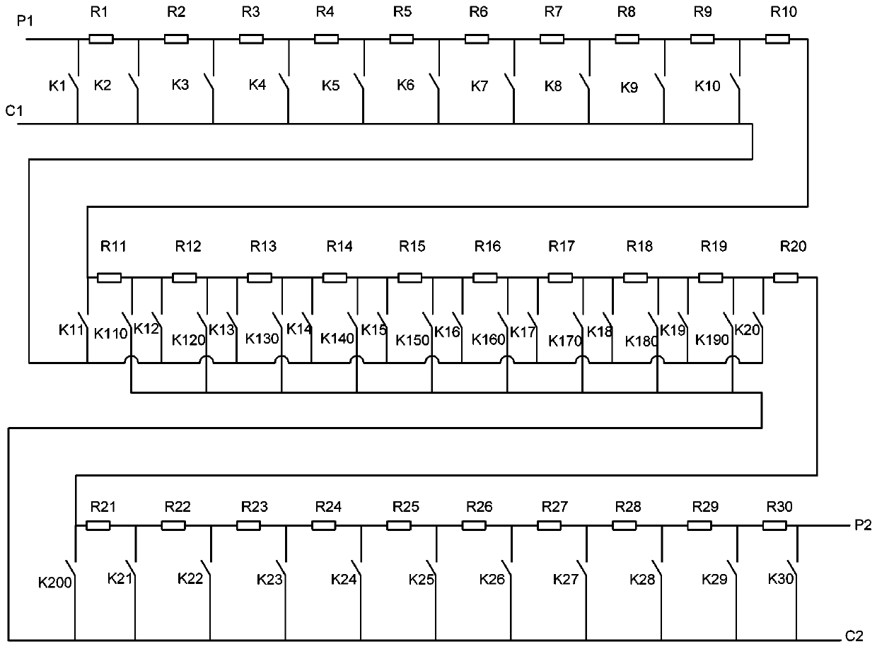
[0076] Such as Figure 12 As shown, repeating Example 1, there are the following differences: the standard resistor system 6 includes ten 1mΩ standard resistors, ten 10mΩ standard resistors and ten 100mΩ standard resistors, and each standard resistor includes four connection terminals, which are respectively current terminals C1, current terminal C2, potential terminal P1 and potential terminal P2, the potential terminals of all standard resistors are connected in series, and the current terminals of all standard resistors are connected in series to form a standard resistor row, and the potential terminals at both ends of the standard resistor row are respectively connected in series with a relay After that, they are respectively connected to the P1 terminal and the P2 terminal on the shell 1, the current terminal C1 of each standard resistor is connected to a relay and then connected to the C1 bus 13, and the current terminal C2 of each standard resistor is connected to a rela...


PUM


Abstract

The invention relates to an earth-continuity tester calibration system. The system comprises a casing, four wiring terminals, and a standard resistor system, a current collection system, a voltage collection system, a C1 relay set, a C2 relay set, a P1 relay set, a P2 relay set, a voltage collection relay set, a current sampling and selection relay set and a main control system which are arrangedin the casing. The system provided by the invention has the advantages that multiple physical standard resistors are adopted to form the standard resistor system for calibration, number combinations and resistance values of the standard resistors participating in the calibration are controlled through relays, and calibration detection is carried out on an earth-continuity tester through the physical standard resistors, so that the physical resistors and relay control modes can be intelligently combined to achieve high flexibility and convenience, the applicability for both the four-terminal wiring method and the two-terminal wiring method is achieved, and the universality, precision and reliability are high.

Description

Technical field: [0001] The invention belongs to the technical field of detection and calibration of a grounding conduction resistance tester, and in particular relates to a calibration system for a grounding conduction resistance tester. Background technique: [0002] The ground connection resistance tester is used to measure the accessible metal casing and the outlet of the electrical equipment powered by the AC grid (such as household appliances, electric heating appliances, medical electrical equipment and measurement, control and laboratory electrical equipment, etc.) An instrument that measures the on-resistance between the safety ground terminals (lines). By outputting AC or DC current, it is applied between the accessible metal shell of the tested object and the safety ground terminal (line) drawn from the device, and the voltage drop generated by the current flowing through the tested object is measured, and then the voltage and current are passed The ratio gives t...

Claims


Application Information

Patent Timeline
IPC IPC(8): G01R35/00
CPCG01R35/007
Inventor 朱小明陆新东郭美玉陈兵宁亮候永辉余昊阳陈昊李东波陈浩李锦华
Owner HENAN PROVINCE INST OF METROLOGY
Why Eureka
Try Eureka