Transmission device with safety pressurization in terminal transmission application
A transmission device and a safe technology, applied in the direction of transformer/inductor cooling, transformer/inductor parts, electrical components, etc., can solve the problems that the transformer cannot transmit power safely and effectively, and the transformer cannot be dissipated heat, etc. Heat exchange, improve heat absorption efficiency, and ensure the effect of heat dissipation efficiency
- Summary
- Abstract
- Description
- Claims
- Application Information
AI Technical Summary
Problems solved by technology
Method used
Image
Examples
Embodiment 1
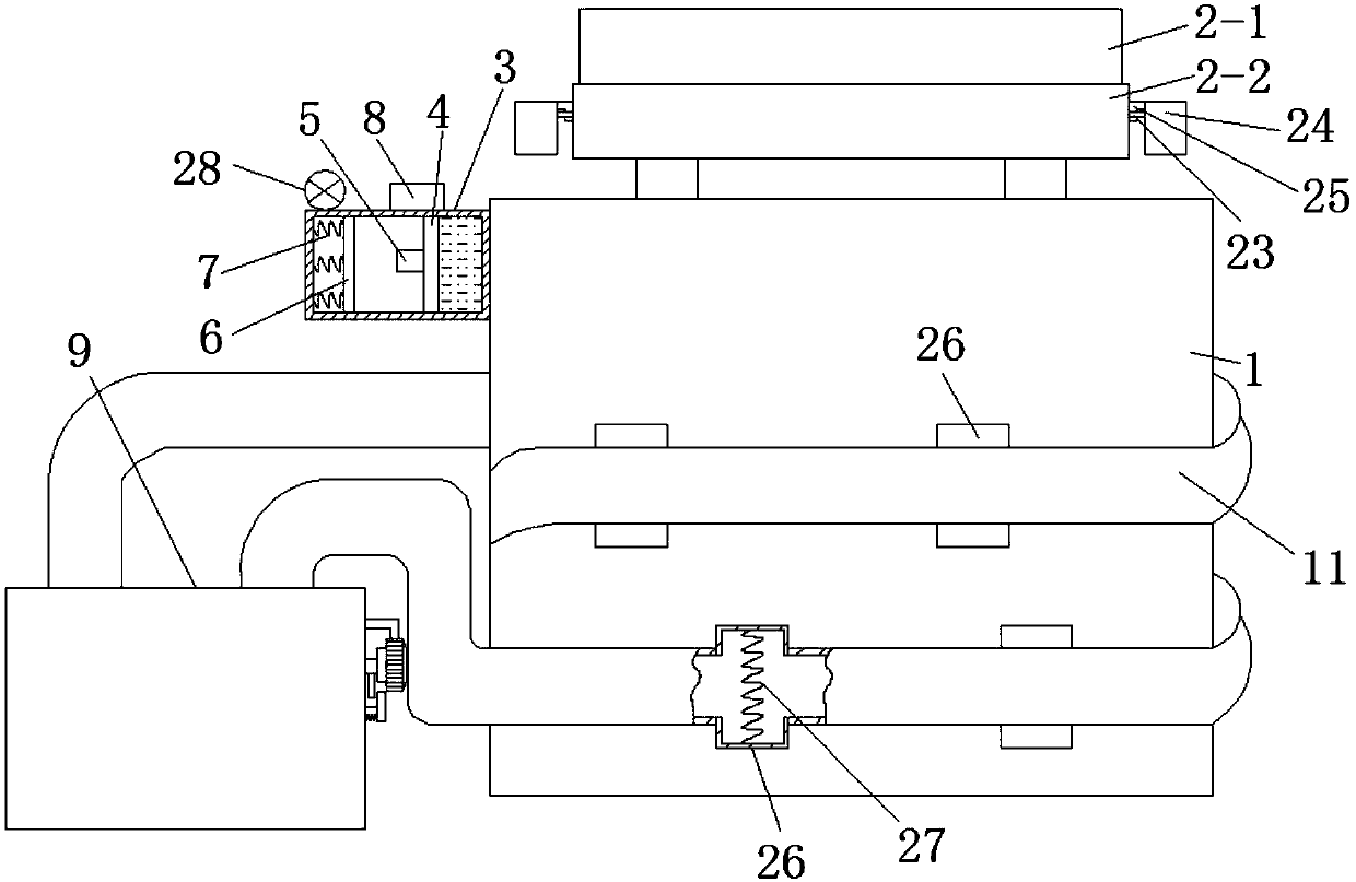
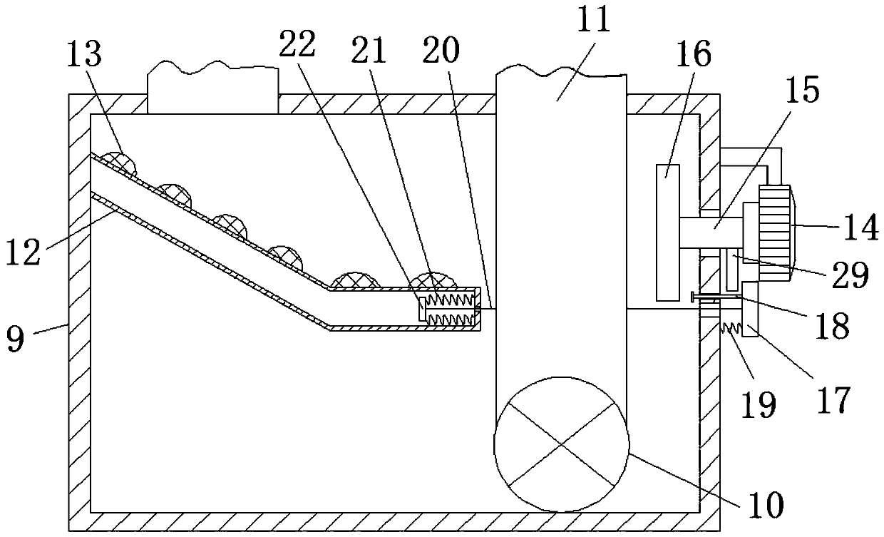
[0060] A transmission device with safety pressurization applied in terminal transmission, which includes a transformer body 1 . In order to ensure that the transformer body 1 can still effectively dissipate heat and transmit electric energy safely and effectively when the cooling oil deteriorates, we propose the following improvements.
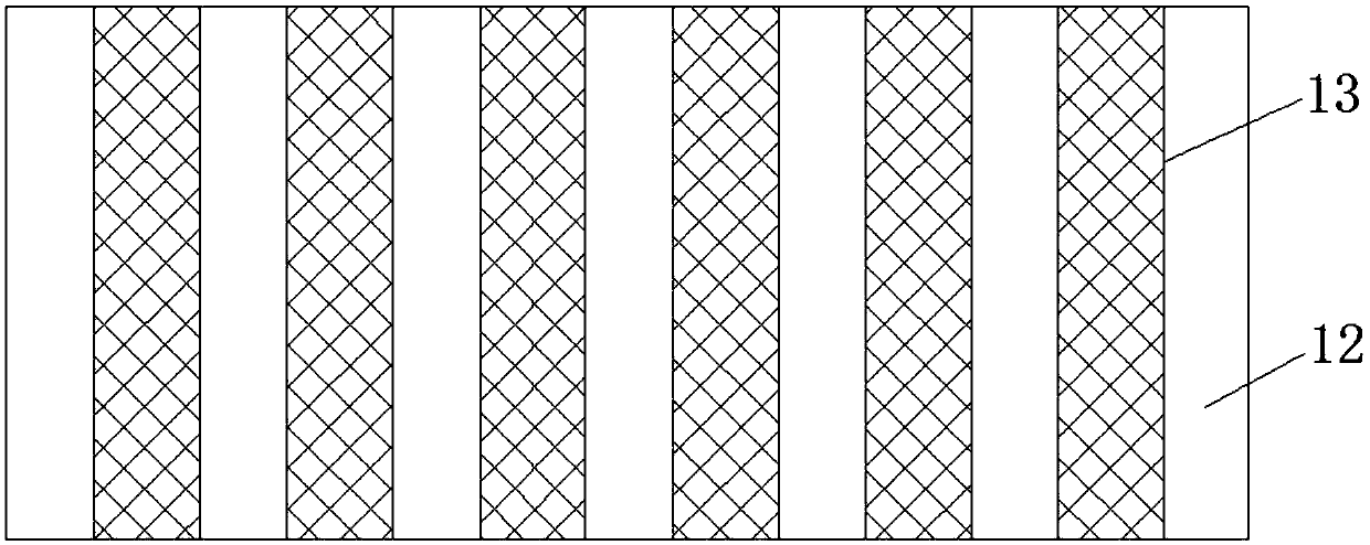
[0061] refer to Figure 1-3 , The transformer body 1 is provided with an auxiliary cooling device. The auxiliary heat dissipation device includes a cooling oil tank 9, an oil pump 10, an oil pipe 11, a baffle plate 12, a convex strip 13, a power motor 14, a rotating rod 15, a fan blade 16 and an induction starting device.
[0062] Wherein, the induction starting device is arranged on the outer wall of the transformer body 1 . The induction starting device includes an induction box 3 , a slide plate 4 , a first conductive sheet 5 , a second conductive sheet 6 and a power source 8 .
[0063] The induction box 3 is installed on the outer wall ...
Embodiment 2
[0074] Such as figure 1 As shown, an oil conservator 2 is installed on the transformer body 1 . When the heat dissipation of the transformer body 1 is not timely, the cooling oil in the transformer body 1 is heated and expands into the oil conservator 2 . In the prior art, the volume of the oil conservator 2 is constant, so that when the cooling oil is excessively heated and expanded, the oil conservator 2 cannot accommodate more cooling oil. To this end, we make the following improvements.
[0075] refer to Figure 4-7 , The oil conservator 2 is a detachable structure. Such as Figure 4 As shown, the oil conservator 2 includes an upper box body 2-1, an upper box body 2-1, a U-shaped hanging handle 23, and an oil loading box 24.
[0076] The lower end of upper box body 2-1 is open shape (as Figure 5 shown); the lower box body 2-2 corresponding to the upper box body 2-1, the upper end of the lower box body 2-2 is open, and the bottom end of the outer side wall of the low...
PUM
 Abstract
Description
Claims
Application Information
 - R&D
- Intellectual Property
- Life Sciences
- Materials
- Tech Scout
- Unparalleled Data Quality
- Higher Quality Content
- 60% Fewer Hallucinations
Browse by: Latest US Patents, China's latest patents, Technical Efficacy Thesaurus, Application Domain, Technology Topic, Popular Technical Reports.
© 2025 PatSnap. All rights reserved.Legal|Privacy policy|Modern Slavery Act Transparency Statement|Sitemap|About US| Contact US: help@patsnap.com


