A transmission device with safety pressurization applied in terminal transmission

A transmission device and a safe technology, which is applied in the direction of transformer/inductor cooling, transformer/inductor parts, electrical components, etc., can solve the problems that the transformer cannot get heat dissipation, the transformer cannot transmit electric energy safely and effectively, and improve Heat absorption efficiency, promotion of heat transfer, and effect of ensuring heat dissipation efficiency

Active Publication Date: 2019-11-01
ANHUI ZENITH ELECTRICITY & ELECTRONICS
View PDF4 Cites 0 Cited by
  • Summary
  • Abstract
  • Description
  • Claims
  • Application Information

AI Technical Summary

Problems solved by technology

[0004] The purpose of the present invention is to provide a transmission device with safety pressurization applied in terminal transmission to solve the problem that when the cooling oil in the transformer deteriorates, the transformer cannot get effective heat dissipation, which leads to the transformer not being able to transmit electric energy safely and effectively question

Method used


Image

  • A transmission device with safety pressurization applied in terminal transmission
  • A transmission device with safety pressurization applied in terminal transmission
  • A transmission device with safety pressurization applied in terminal transmission

Examples


Embodiment 1

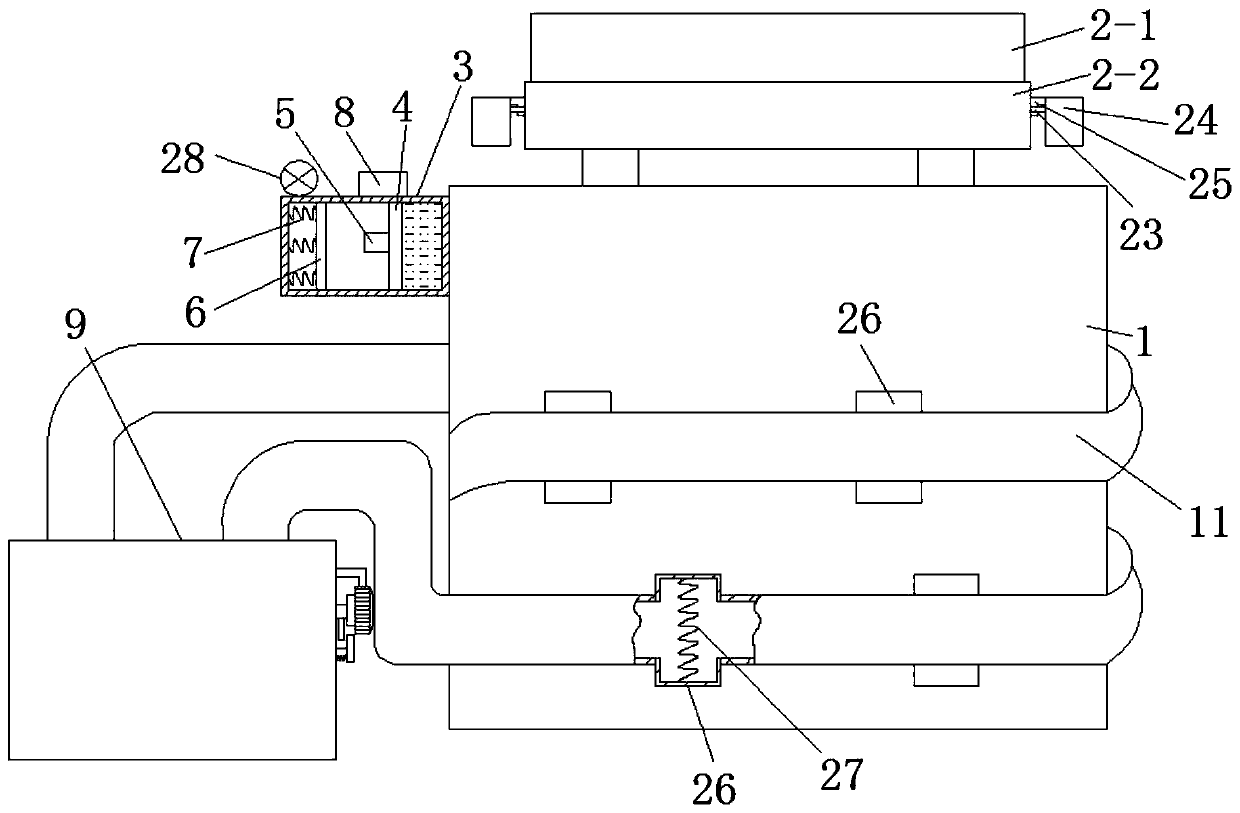
[0060] A transmission device with safety pressurization applied in terminal transmission, which includes a transformer body 1 . In order to ensure that the transformer body 1 can still effectively dissipate heat and transmit electric energy safely and effectively when the cooling oil deteriorates, we propose the following improvements.

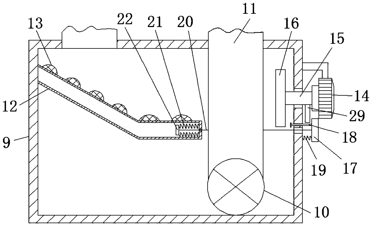
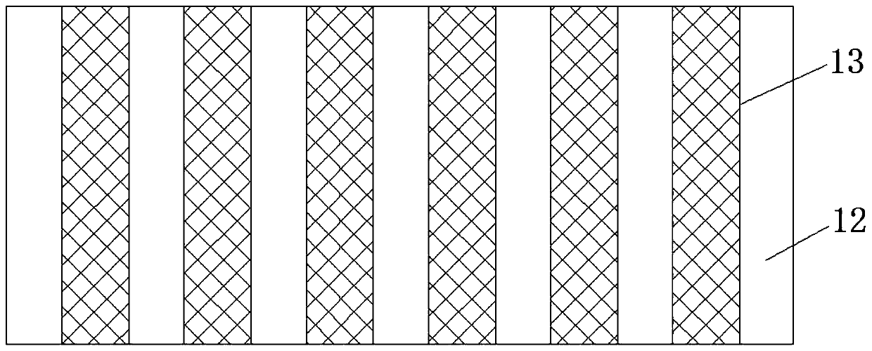
[0061] refer to Figure 1-3 , The transformer body 1 is provided with an auxiliary cooling device. The auxiliary heat dissipation device includes a cooling oil tank 9, an oil pump 10, an oil pipe 11, a baffle plate 12, a convex strip 13, a power motor 14, a rotating rod 15, a fan blade 16 and an induction starting device.

[0062] Wherein, the induction starting device is arranged on the outer wall of the transformer body 1 . The induction starting device includes an induction box 3 , a slide plate 4 , a first conductive sheet 5 , a second conductive sheet 6 and a power source 8 .

[0063] The induction box 3 is installed on the outer wall ...

Embodiment 2

[0074] Such as figure 1 As shown, an oil conservator 2 is installed on the transformer body 1 . When the heat dissipation of the transformer body 1 is not timely, the cooling oil in the transformer body 1 is heated and expands into the oil conservator 2 . In the prior art, the volume of the oil conservator 2 is constant, so that when the cooling oil is excessively heated and expanded, the oil conservator 2 cannot accommodate more cooling oil. To this end, we make the following improvements.

[0075] refer to Figure 4-7 , The oil conservator 2 is a detachable structure. Such as Figure 4 As shown, the oil conservator 2 includes an upper box body 2-1, an upper box body 2-1, a U-shaped hanging handle 23, and an oil loading box 24.

[0076] The lower end of upper box body 2-1 is open shape (as Figure 5 shown); the lower box body 2-2 corresponding to the upper box body 2-1, the upper end of the lower box body 2-2 is open, and the bottom end of the outer side wall of the low...


PUM


Abstract

The invention discloses a transmission device with safety pressurization in terminal transmission application. The transmission device comprises a transformer body, wherein an auxiliary cooling deviceis arranged on the transformer body and comprises a cooling oil tank, an oil pump, an oil pipe, a baffle plate, convex strips, a power motor, a rotation rod, a fan blade and an induction starting device. Cooling water in an induction box is heated and evaporated and become a gas, a first conduction piece is pushed to move leftwards and contact with a second conduction piece, a series circuit is connected, and the oil pump and the power motor are started; heat absorption oil of the cooling oil box is pumped into the oil pipe by the oil pump so as to absorb heat of the transformer body, and thecooling efficiency of the transformer body is ensured; and when heat absorption oil returns to the cooling oil tank after heat exchange, and the heat absorption oil after heat exchange can slowly descend along an inclination segment of the baffle plate, at the moment, the fan blade is driven to rotate by the power motor so as to performing air cooling on the slowly-descending heat absorption oilafter heat exchange, and cycle heat absorption of the heat absorption oil at the next time is facilitated.

Description

technical field [0001] The invention relates to the technical field of power transmission devices, in particular to a transmission device with safety pressurization applied in terminal transmission. Background technique [0002] In the process of power transmission, a transformer is used. A power transformer is a static electrical device that is used to change an AC voltage (current) of a certain value into another voltage (current) with the same frequency or several different values. When the primary winding is supplied with alternating current, alternating magnetic flux is generated, and the alternating magnetic flux induces an alternating electromotive force in the secondary winding through the magnetic conduction of the iron core. The level of the secondary induced electromotive force is related to the number of turns of the primary and secondary windings, that is, the voltage is proportional to the number of turns. Its main function is to transmit electrical energy. ...

Claims


Application Information

Patent Timeline
Patent Type & Authority Patents(China)
IPC IPC(8): H01F27/14H01F27/08
CPCH01F27/085H01F27/14
Inventor 王勇张小龙韩周明小慧张孟项云飞王永成谷江涛常俊杰
Owner ANHUI ZENITH ELECTRICITY & ELECTRONICS
Why Eureka
Try Eureka