Phased-array antenna beam control system

A phased array antenna and beam control technology, applied in the direction of antennas, electrical components, etc., can solve problems such as increased complexity of delay devices, and achieve the effects of improving dispersion problems, improving performance, and good adaptability

Inactive Publication Date: 2019-04-05
江苏万邦微电子有限公司
View PDF3 Cites 11 Cited by
  • Summary
  • Abstract
  • Description
  • Claims
  • Application Information

AI Technical Summary

Problems solved by technology

In order to ensure wider in-band performance, the complexity of the delayer is bound to increase

Method used


Image

  • Phased-array antenna beam control system
  • Phased-array antenna beam control system
  • Phased-array antenna beam control system

Examples


Embodiment Construction

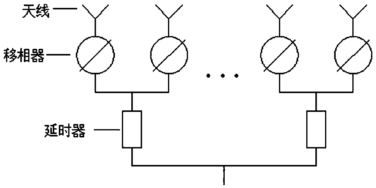
[0040] According to the figure, there are phase shifters and delayers on the phased array antenna, and the two phase shifter channels on the sub-array level of the phased array antenna correspond to a delayer, and the phase shifter is calculated by the delay residual method Then use the intermediate frequency follow-up method to calculate the phase-shift code. The specific steps are as follows:

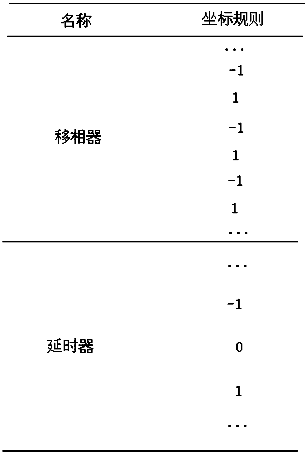
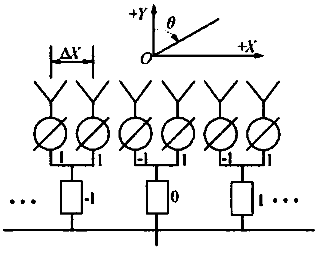
[0041] Step 1: Set the number of delay channels corresponding to the sub-array delayers of the phased array antenna to be an odd number, and the delay channels are designed symmetrically about the center of the array, so that the coordinate rules of the phased array antenna are obtained; And set the phaser coordinate step to 2.

[0042] Step 2: Estimate the wave control code, set the sub-array system of the phased array antenna as the coordinate system, the normal direction of radiation is +Y, the scanning angle θ in the normal direction is 0°, scanning in the +X direction is positive...


PUM


Abstract

Disclosed is a phased-array antenna beam control system. A phased-array antenna is provided with phase shifters and a delayer; the two phase shifter channels in the sub-array level of the phased-arrayantenna correspond to one delayer. A phase shifter control code is calculated through a delay residual method, and then the phase shifting code is calculated by utilizing an intermediate frequency follow-up method. On the basis of the delay residual method, the intermediate frequency follow-up method is provided, and by adoption of the intermediate frequency follow-up method, the indexes of antenna broadband pointing error, gain, grating lobes and the like can be improved through algorithm optimization on the basis of not changing the hardware design of the delayer; and the algorithm not onlyhas high adaptability, but also can improve the performance of the antenna broadband directional diagram.

Description

technical field [0001] The invention relates to the field of antennas, in particular to a phased array antenna beam control system. Background technique [0002] The phased array radars currently on the market have many advantages such as anti-interference, high resolution, and low probability of interception because of their wide instantaneous bandwidth. Therefore, it is widely used in radar fields such as passive detection, target recognition, remote sensing ranging, and signal concealment. However, phased array antennas that only use phase shifters to adjust the beam pointing will have dispersion phenomenon in the beam pointing, which seriously restricts the instantaneous bandwidth performance of the antenna. Moreover, with the increase of radar functions and the substantial improvement of performance, higher requirements are put forward for the bandwidth of the antenna system. The working bandwidth of the multifunctional radar test system has reached 6GHz-18GHz. In ord...

Claims


Application Information

Patent Timeline
Patent Type & Authority Applications(China)
IPC IPC(8): H01Q3/36
CPCH01Q3/2694
Inventor 朱勤辉张林赵星
Owner 江苏万邦微电子有限公司
Why Eureka
Try Eureka