Drilling machine

A drilling machine and worktable technology, which is applied to the components of the boring machine/drilling machine, boring/drilling, drilling/drilling equipment, etc. Achieve the effect of improving processing efficiency, convenient operation and small vibration

Inactive Publication Date: 2019-04-12
ZHEJIANG XILING
View PDF9 Cites 2 Cited by
  • Summary
  • Abstract
  • Description
  • Claims
  • Application Information

AI Technical Summary

Problems solved by technology

When the power supply voltage is unstable, or the influence of external force, or the material hardness of the workpiece is uneven, the speed of the drilling machine will be unstable and the cutting quality will be affected.
This greatly affects the production efficiency of the enterprise and increases the production cost of the enterprise.

Method used


Image

  • Drilling machine
  • Drilling machine
  • Drilling machine

Examples


Embodiment 1

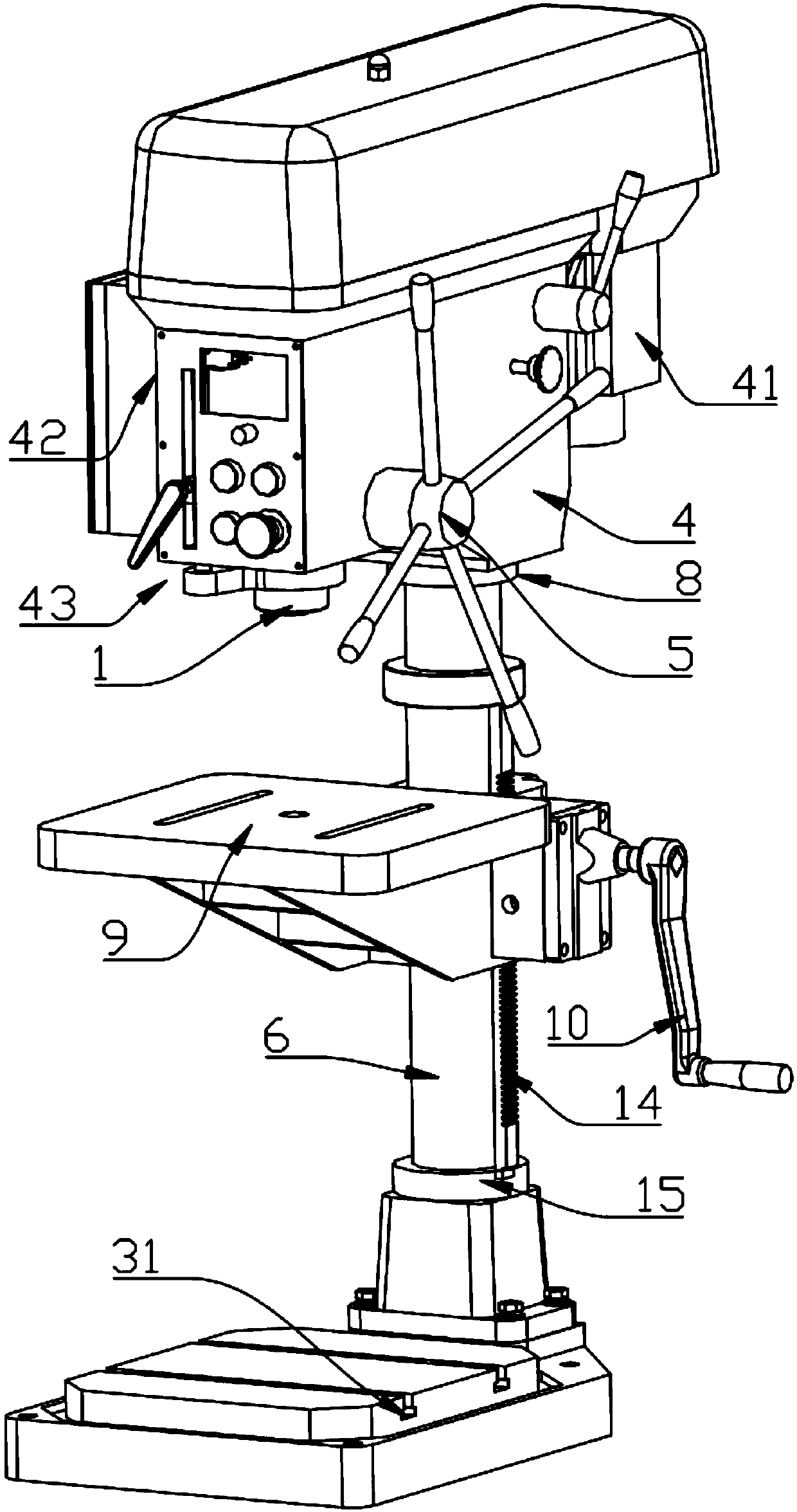
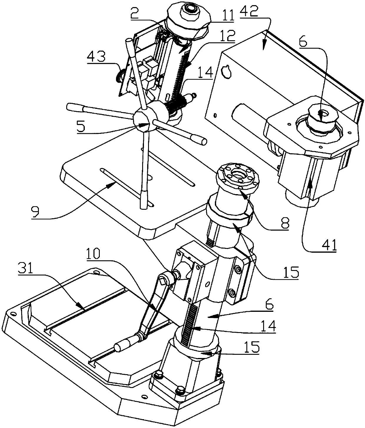
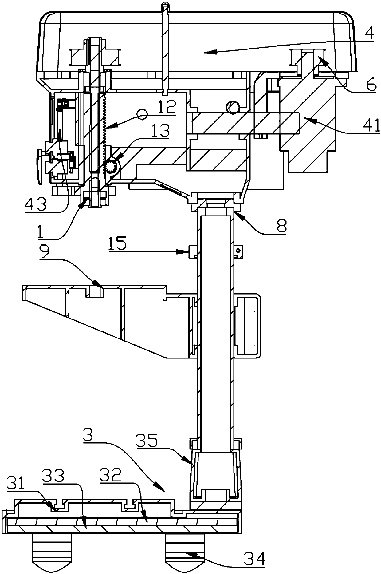
[0033] Embodiment one: if Figure 1-3 As shown, a drilling machine includes a base 31, a support rod 7, a workbench 9 and a machine head. The base 31 is provided with a support rod 7, and the support rod 7 is covered with a workbench 9. The workbench One side of the 9 is provided with a rotary rocker 10 capable of controlling the slide of the workbench 9 on the support column 7, and the upper end of the support column 7 is equipped with a machine head through a connecting flange 8, and the machine head includes a head frame 4, is arranged on One side of the head frame 4 and the rotating disk 5 that drives the main shaft 2 to move up and down, the gear box 67 and the permanent magnet motor 41 that drives the main shaft 2 to rotate, the output shaft of the permanent magnet motor 41 is connected with the pulley 6, and the permanent magnet motor 41 is connected to the pulley 6. One side of the magneto 41 is provided with a frequency converter 42, which is connected to each other t...

Embodiment 2

[0041] Embodiment two: if Figure 4-7 As shown: this embodiment is basically the same as Embodiment 1, the difference is that the side of the workbench 9 is provided with side baffles 22, the number of the side baffles 22 is three, and the three are vertically arranged The side baffles 22 are respectively positioned at both sides and the rear portion of the workbench 9, the front portion of the workbench 9 is provided with a front baffle 23, and the height of the front baffle 23 is lower than the side baffles 22; There is at least one group of fan units, and the side baffle 22 has a first air outlet 221 and a second air outlet 222, and the first air outlet 221 and the second air outlet 222 are connected with the air outlet pipe of the fan unit; the other side baffle 22 The outer side is connected with the storage body 24 , the lower part of the storage body 24 is a storage portion 240 , and a storage cavity 242 is formed in the storage portion 240 .

[0042] This technical so...


PUM


Abstract

The invention belongs to the technical field of machinery, in particular to a drilling machine. The drilling machine comprises a drill bit, a main shaft arranged above the drill bit and driving the drill bit to rotate, a head frame, a rotary disc rotatably arranged on one side of the head frame, a belt wheel arranged on the head frame, a base, a supporting column arranged on the base, a connectingflange sleeving on the supporting column, a working table and a rotary shaking arm, wherein the rotary shaking arm is arranged on one side of the working table and can control the working table to slide on the supporting column, and the rotary shaking arm is movably connected with the drilling machine working table; and a permanent magnet motor with a frequency changing function is arranged on one side of the head frame, an output shaft of the permanent magnet motor is connected with the belt wheel, a frequency changer is arranged on one side of the permanent magnet motor and connected with the permanent magnet motor through a wire, the frequency changer is mounted on the head frame, and a plurality of control devices used for adjusting speed and starting and stopping are arranged on thefrequency changer. The drilling machine has stable structure, stepless speed adjustment and long service life.

Description

technical field [0001] The invention belongs to the technical field of machinery, in particular to a drilling machine. Background technique [0002] At present, drilling machines are generally speed-regulated through multi-stage pulleys. Due to the structural characteristics, the speed regulation of the existing drilling machine is inconvenient. When adjusting the speed, it is necessary to remove the pulley shell and adjust the position of the belt. The speed ratio of the drilling machine has a small adjustment range, generally within 1:10. Because of the step speed regulation, the optimal speed required by the drilling machine for drilling and cutting cannot be obtained. The larger the speed ratio of the drilling machine, the larger the diameter of the pulley, which increases the volume of the drilling machine. When the power supply voltage is unstable, or the influence of external force, or the material hardness of the workpiece is uneven, the speed of the drilling mac...

Claims


Application Information

Patent Timeline
Patent Type & Authority Applications(China)
IPC IPC(8): B23B39/00B23B47/00B23Q11/00B23Q11/08
CPCB23B39/00B23B47/00B23Q11/0032B23Q11/0096B23Q11/08
Inventor 杨学良
Owner ZHEJIANG XILING
Why Eureka
Try Eureka