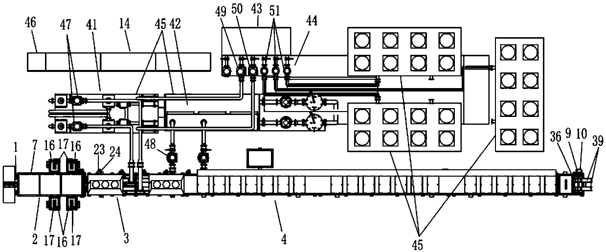
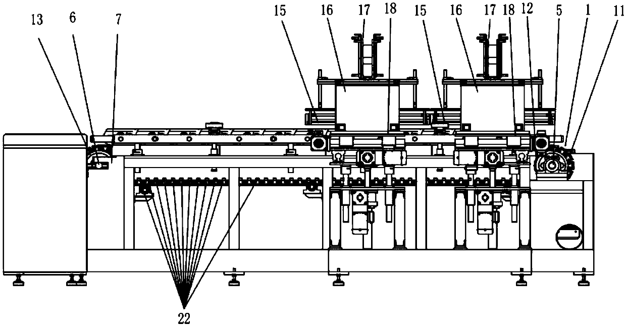
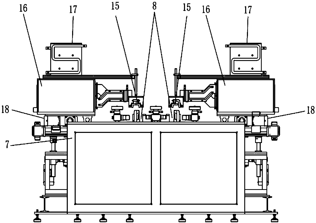
Caterpillar track section induction quenching and tempering machine tool and circuit protection method

A technology of induction hardening and chain rail joints, applied in the direction of quenching device, furnace type, furnace, etc., can solve the problems of large application field limitation, low degree of automation of equipment, low production efficiency, etc., to achieve stable and reliable equipment and perfect detection. Control function, high production efficiency effect

Pending Publication Date: 2019-04-12
十堰高周波科工贸有限公司
View PDF10 Cites 2 Cited by
  • Summary
  • Abstract
  • Description
  • Claims
  • Application Information

AI Technical Summary

Problems solved by technology

[0002] Most of the induction hardening equipment in the prior art adopts static induction heating and quenching technology, while the dynamic continuous induction heating and quenching equipment adopts the authorized announcement number CN208234951U application number: 2018207241905 Utility model name: continuous induction hardening and tempering equipment for shaft parts. The equipment is only suitable for single-track transportation of cylindrical bearing parts, and the biaxial rubbing of the workpiece makes the workpiece undergo induction heating and quenching while rotating. The single-track transportation leads to low production efficiency and low automation of the equipment, and the application field is limited. It is suitable for continuous induction heating and quenching process of large and heavy parts such as chain rail links for military tanks and chain rail links for construction machinery. There has been no good solution to this defect

Method used


Image

  • Caterpillar track section induction quenching and tempering machine tool and circuit protection method
  • Caterpillar track section induction quenching and tempering machine tool and circuit protection method
  • Caterpillar track section induction quenching and tempering machine tool and circuit protection method

Examples


Embodiment Construction

[0028] The technical solutions of the present invention will be clearly and completely described below in conjunction with the accompanying drawings. In the description of the present invention, it should be noted that the terms "center", "upper", "lower", "left", "right", "vertical", "horizontal", "inner", "outer" etc. The indicated orientation or positional relationship is based on the orientation or positional relationship shown in the drawings, and is only for the convenience of describing the present invention and simplifying the description, rather than indicating or implying that the referred device or element must have a specific orientation, or in a specific orientation. construction and operation, therefore, should not be construed as limiting the invention. In addition, the terms "first", "second", and "third" are used for descriptive purposes only, and should not be construed as indicating or implying relative importance.

[0029] In the description of the present...


PUM


Abstract

A caterpillar track section induction quenching and tempering machine tool comprises modular conveying devices in groups. Various functional components and sealing frames are arranged on the modular conveying devices to form an induction heating chamber, a liquid spray quenching chamber and a tempering induction chamber correspondingly, the modular conveying devices comprise the modular plate typechain wheel conveying devices and the modular roller wheel conveying devices, the induction heating chamber comprises inductors, quenching transformers and three-dimensional sliding tables, the two quenching transformers on the same side of two tracks are connected in parallel to a same IGBT power unit, the two sets of inductors in two columns are suspended over the front track and the rear track, the liquid spray quenching chamber comprises the multiple stages of modular roller wheel conveying devices which are each provided with a liquid spray pipeline and a liquid spray device right opposite to the top of two roll gangs, the bottoms of the two roll gangs are provided with quenching liquid collection grooves, a tempering induction station comprises three stages of tempering induction chambers, a tunnel tempering inductor is suspended above two caterpillar tracks in a right opposite mode and electrically connected with a tempering capacitor box, and the tempering capacitor box is electrically connected with an IGBT tempering power source.

Description

technical field [0001] The invention belongs to the technical field of electromechanical integration of electromagnetic induction heating and quenching, and specifically relates to the technical field of mechanical manufacturing and circuit control design of chain rail link induction quenching and tempering machine tools. Background technique [0002] Most of the induction hardening equipment in the prior art adopts static induction heating and quenching technology, while the dynamic continuous induction heating and quenching equipment adopts the authorized announcement number CN208234951U application number: 2018207241905 Utility model name: continuous induction hardening and tempering equipment for shaft parts. The equipment is only suitable for single-track transportation of cylindrical bearing parts, and the biaxial rubbing of the workpiece makes the workpiece undergo induction heating and quenching while rotating. The single-track transportation leads to low production e...

Claims


Application Information

Patent Timeline
Patent Type & Authority Applications(China)
IPC IPC(8): C21D1/667C21D1/10C21D9/00C21D11/00
CPCC21D1/10C21D1/667C21D9/0087C21D11/00Y02P10/25
Inventor 刘成川何中永何正龙刘立茂
Owner 十堰高周波科工贸有限公司
Why Eureka
Try Eureka