Novel volute structure of centrifugal machine

A centrifuge and volute technology, applied in the field of centrifuges, can solve the problems of difficulty in the arrangement of various components of the aerodynamic part of the centrifuge, reduced operating stability of the centrifuge, and lack of versatility, etc., to increase the critical speed, reduce the length, The effect of improving versatility

Pending Publication Date: 2019-04-12
FUJIAN SNOWMAN
View PDF0 Cites 0 Cited by
  • Summary
  • Abstract
  • Description
  • Claims
  • Application Information

AI Technical Summary

Problems solved by technology

[0004] Among them, in the structure of two-stage and multi-stage centrifugal compressors, in order to reduce the length of the cantilever end of the main shaft and enhance the stability, it is often necessary to design the pneumatic part of the multi-stage compression to be very compact. The number of components involved in the pneumatic part of the centrifuge Many, which makes the arrangement of the various components of the pneumatic part of the centrifuge difficult
In particular, there are deficiencies in the design of the volute, which not only has no versatility and high cost, but also reduces the stability and performance of the centrifuge

Method used


Image

  • Novel volute structure of centrifugal machine
  • Novel volute structure of centrifugal machine

Examples


Embodiment

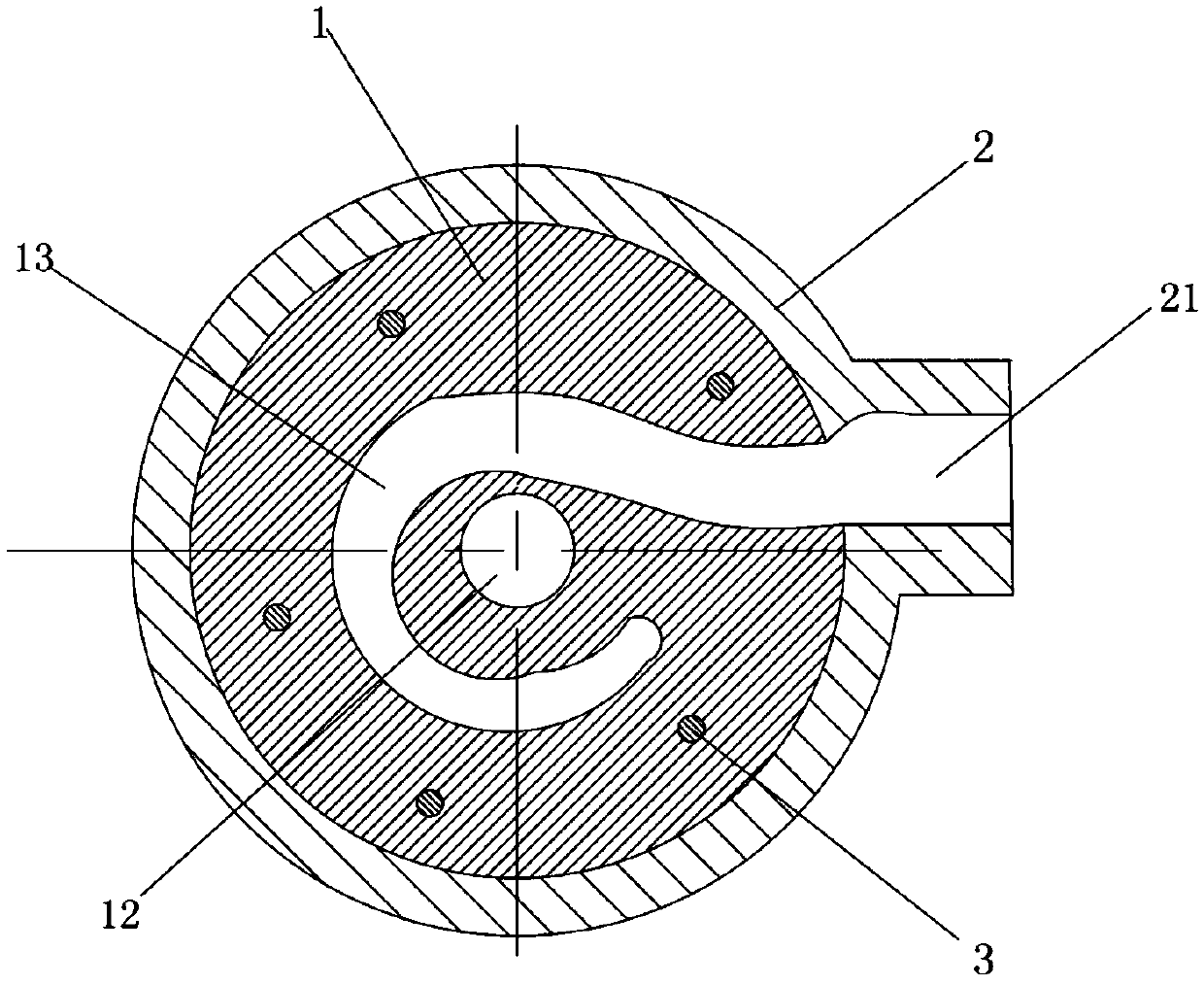
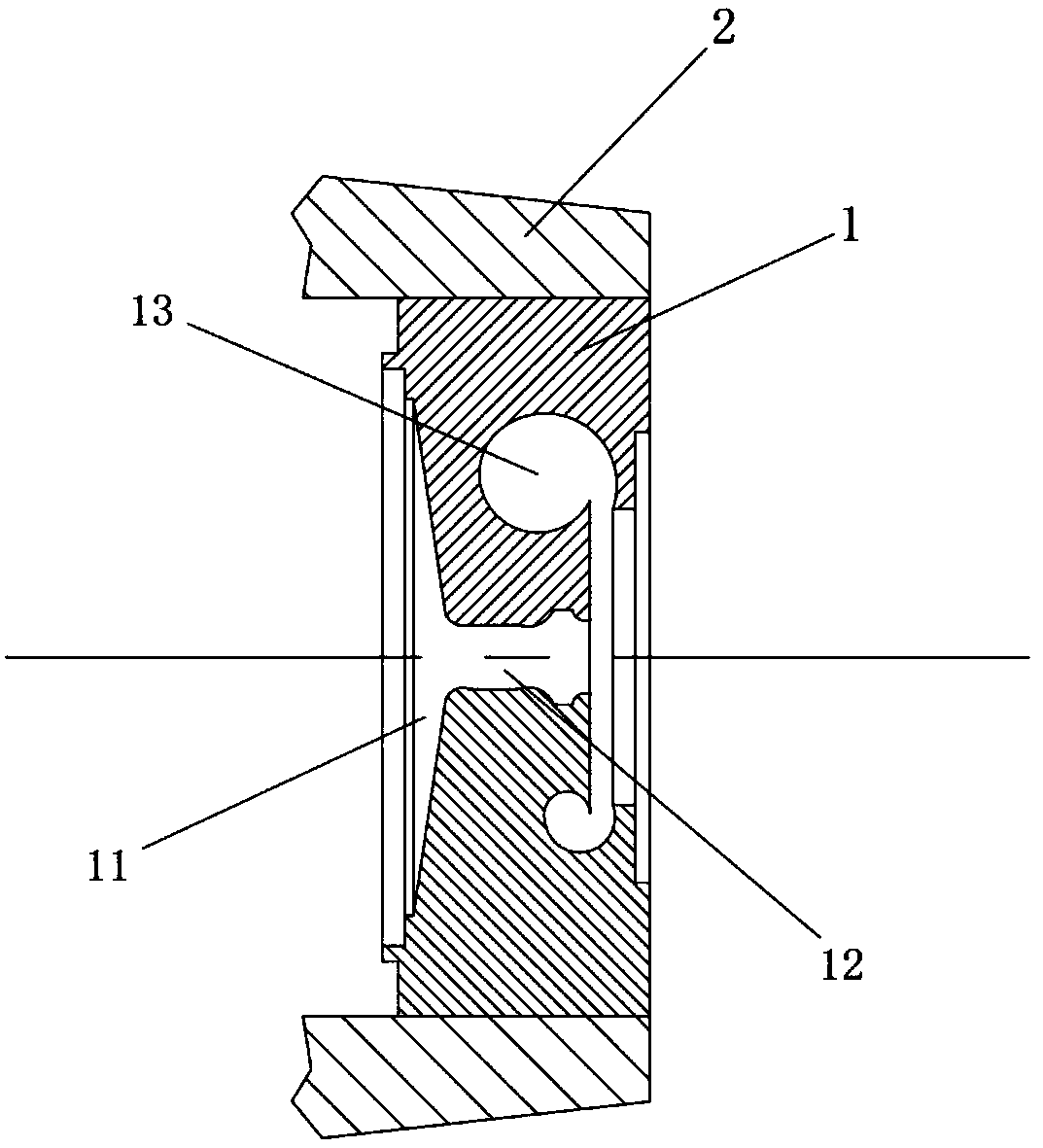
[0027] The volute structure of a new centrifuge, such as figure 1 , figure 2 As shown, it includes an inner volute 1 and an outer volute 2, the cross-sectional shape of the inner volute 1 is circular, and it is arranged in the outer volute 2; the inner volute 1 and the outer volute 2 pass through They are connected into one body in the form of clearance fit, and fixed on the motor casing for transmission by screws 3, so that centrifuges with similar cooling capacity can share the same specification of the outer volute 2; the outer volute 2 is provided with Air outlet channel 21; the inner volute 1 is provided with a relief groove 11 and a relief through hole 12 for the installation of other centrifuge components such as a reflux assembly, a diffuser and an impeller; the relief groove 11 and The through hole 12 is connected; the inner volute 1 is provided with a bend 13, and the cross section of the bend 13 in the direction of the vertical axis is a bilaterally symmetrical vo...


PUM


Abstract

The invention discloses a novel volute structure of a centrifugal machine. The novel volute structure of the centrifugal machine comprises an inner volute and an outer volute, wherein the inner voluteis arranged in the outer volute, the outer volute is provided with an air outlet channel, and the inner volute is provided with a receding groove and a receding through hole; the receding groove communicates with the receding through hole; and a curve is arranged in the inner volute and communicates with the air outlet channel, and the curve communicates with the receding groove and the recedingthrough hole. The novel volute structure of the centrifugal machine is simple in structure and is applied to the centrifugal machine to be matched with an impeller and a diffuser so that the guiding and diffusing effects of the volutes can be better achieved, the pneumatic loss is reduced, and the isentropic efficiency is improved; the friction between the flow and the walls of the volutes is reduced, and the operating noise of the centrifugal machine is lowered; and the universality of the volutes is improved, and economic benefits are increased.

Description

technical field [0001] The invention relates to the technical field of centrifuges, in particular to a novel volute structure of a centrifuge. Background technique [0002] The centrifuge uses the motor to drive the impeller of the main shaft of the compressor to rotate. Under the action of centrifugal force, the gas is thrown into the diffuser, and a thin zone is formed in the middle of the working wheel. The gas in front enters the impeller from the intake part in the middle of the working wheel. The wheel rotates continuously, and the gas is continuously thrown out, thereby maintaining the continuous flow of gas in the air compressor. The pressure of the gas is increased due to centrifugal action, and it leaves the working wheel at a high speed. The speed of the gas is gradually reduced through the diffuser, and the kinetic energy is converted into static pressure energy, which further increases the pressure. [0003] With the development of the economic level, centrifug...

Claims


Application Information

Patent Timeline
Patent Type & Authority Applications(China)
IPC IPC(8): F04D29/42F04D29/66
CPCF04D29/4206F04D29/661
Inventor 林汝捷黄荣高
Owner FUJIAN SNOWMAN
Why Eureka
Try Eureka