Voltage stabilizing aircraft skin clamping system and method

An aircraft skin and voltage stabilizing technology, which is applied to mechanical equipment, fluid pressure actuators, servo motors, etc., to achieve the effects of smooth commutation, stable commutation and stable pressure

Pending Publication Date: 2019-04-12
德阳元亨机械制造有限公司
View PDF2 Cites 1 Cited by
  • Summary
  • Abstract
  • Description
  • Claims
  • Application Information

AI Technical Summary

Problems solved by technology

[0007] In order to overcome the defects of the above-mentioned prior art, the present invention proposes a system and method for clamping the skin of an aircraft with constant pressure, which can prevent the clamping force from being too large or too small when the jaws are clamping the skin , the clamping force has high precision, which makes the system reversing smoothly; when the valve port, spool or other parts of the reversing valve leak and lose pressure, the hydraulic oil is supplied to the rodless chamber of the hydraulic cylinder through the accumulator, and the rodless The pressure of the cavity will not decrease, so that the pressure of the jaws used by the hydraulic pressure is stable. During the process of stretching the skin of the jaws, the pressure of the jaws is maintained so that the clamping force remains unchanged and the stretching effect will not be affected.

Method used


Image

  • Voltage stabilizing aircraft skin clamping system and method
  • Voltage stabilizing aircraft skin clamping system and method
  • Voltage stabilizing aircraft skin clamping system and method

Examples


Embodiment 1

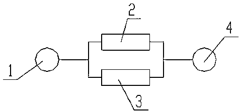
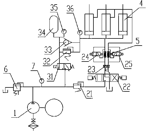
[0040] Such as Figures 1 to 3 As shown, a pressure-stabilizing clamping aircraft skin system includes a hydraulic pump 1 and a hydraulic cylinder 4, and is characterized in that a pressure-stabilizing unit 2 and a pressure-holding unit are arranged in parallel between the hydraulic pump 1 and the hydraulic cylinder 4 3;

[0041] The pressure stabilizing unit 2 includes a decompression valve A21 sequentially connected with the hydraulic pump 1, an electro-hydraulic reversing valve 22 and a hydraulic control check valve 23, and the hydraulic control check valve 23 is connected with an electromagnetic reversing valve A24 and an electromagnetic reversing valve A24. The reversing valve B25, the electromagnetic reversing valve A24 and the electromagnetic reversing valve B25 are arranged side by side, the rodless chamber of the hydraulic cylinder 4 is connected with the electromagnetic reversing valve A24, and the rod chamber of the hydraulic cylinder 4 is connected to the electroma...

Embodiment 2

[0045] Such as Figures 1 to 3 As shown, a pressure-stabilizing clamping aircraft skin system includes a hydraulic pump 1 and a hydraulic cylinder 4, and is characterized in that a pressure-stabilizing unit 2 and a pressure-holding unit are arranged in parallel between the hydraulic pump 1 and the hydraulic cylinder 4 3;

[0046] The pressure stabilizing unit 2 includes a decompression valve A21 sequentially connected with the hydraulic pump 1, an electro-hydraulic reversing valve 22 and a hydraulic control check valve 23, and the hydraulic control check valve 23 is connected with an electromagnetic reversing valve A24 and an electromagnetic reversing valve A24. The reversing valve B25, the electromagnetic reversing valve A24 and the electromagnetic reversing valve B25 are arranged side by side, the rodless chamber of the hydraulic cylinder 4 is connected with the electromagnetic reversing valve A24, and the rod chamber of the hydraulic cylinder 4 is connected to the electroma...

Embodiment 3

[0055] Such as Figures 1 to 3 As shown, a pressure-stabilizing clamping aircraft skin system includes a hydraulic pump 1 and a hydraulic cylinder 4, and is characterized in that a pressure-stabilizing unit 2 and a pressure-holding unit are arranged in parallel between the hydraulic pump 1 and the hydraulic cylinder 4 3;

[0056] The pressure stabilizing unit 2 includes a decompression valve A21 sequentially connected with the hydraulic pump 1, an electro-hydraulic reversing valve 22 and a hydraulic control check valve 23, and the hydraulic control check valve 23 is connected with an electromagnetic reversing valve A24 and an electromagnetic reversing valve A24. The reversing valve B25, the electromagnetic reversing valve A24 and the electromagnetic reversing valve B25 are arranged side by side, the rodless chamber of the hydraulic cylinder 4 is connected with the electromagnetic reversing valve A24, and the rod chamber of the hydraulic cylinder 4 is connected to the electroma...


PUM

PropertyMeasurementUnit
diameteraaaaaaaaaa

Abstract

The invention discloses voltage stabilizing aircraft skin clamping system and method. The voltage stabilizing aircraft skin clamping system comprises a hydraulic pump and a hydraulic cylinder, whereina voltage stabilizing unit and a pressure maintaining unit are arranged between the hydraulic pump and the hydraulic cylinder in parallel; the voltage stabilizing unit comprises a reducing valve A, an electro-hydraulic directional valve and a hydraulic control one-way valve sequentially connected with the hydraulic cylinder; the hydraulic control one-way valve is connected with an electromagneticdirectional valve A and an electromagnetic directional valve B; the electromagnetic directional valve A and the electromagnetic directional valve B are arranged in parallel; a rodless cavity of the hydraulic cylinder is connected with the electromagnetic directional valve A; a rod cavity of the hydraulic cylinder is connected with the electromagnetic directional valve B; the pressure maintainingunit comprises an electromagnetic directional valve C connected with the hydraulic pump; the electromagnetic directional valve C is connected with a reducing valve B, a one-way valve and an energy accumulator; and the reducing valve B and the one-way valve are arranged in parallel. When a skin is clamped through a jaw, the phenomenon that a clamping force is too big or too small cannot occur, thesystem is stable in reversing, the pressure of the jaw is maintained, the clamping force is unchanged, and a stretching effect cannot be influenced.

Description

technical field [0001] The invention belongs to the technical field of aviation aircraft manufacturing, and in particular relates to a pressure-stabilizing clamping aircraft skin system and method. Background technique [0002] Skin parts are exterior parts that form and maintain the aerodynamic shape of the aircraft. Stretch forming (abbreviated as stretch forming) is a process method of overmolding by molds, and it is one of the main forming methods for aircraft skin parts. Longitudinal stretch forming is one of the process forms of skin stretch forming, which mainly forms skin parts with small longitudinal curvature and large transverse curvature. When designing the skin longitudinal stretching process, the curved jaw clamping is realized by designing the relative rotation angle between the sub-clamps in the clamp group, so as to realize the curvature forming of the end of the skin wool. The parameter design of the curved jaw is the longitudinal tension. It is an importa...

Claims


Application Information

Patent Timeline
Patent Type & Authority Applications(China)
IPC IPC(8): F15B1/02F15B11/16B21D24/08
CPCF15B1/02B21D24/08F15B11/16
Inventor 王和德黄学刚王东
Owner 德阳元亨机械制造有限公司
Why Eureka
Try Eureka