Renewable energy source-based room temperature control method and system

A technology of renewable energy and control system, applied in solar heating system, heating system, hot water central heating system, etc., can solve the problem of low quality of hot water, and achieve the effect of good quality

Inactive Publication Date: 2019-04-12
NORTH CHINA ELECTRIC POWER UNIV (BAODING)
View PDF5 Cites 1 Cited by
  • Summary
  • Abstract
  • Description
  • Claims
  • Application Information

AI Technical Summary

Problems solved by technology

During this process, the supply and return water are mixed in the tank, which results in a lower quality hot water pumped into the heater, requiring constant supply of heat to the tank to increase the temperature of the water in the tank

Method used


Image

  • Renewable energy source-based room temperature control method and system
  • Renewable energy source-based room temperature control method and system

Examples


Embodiment 1

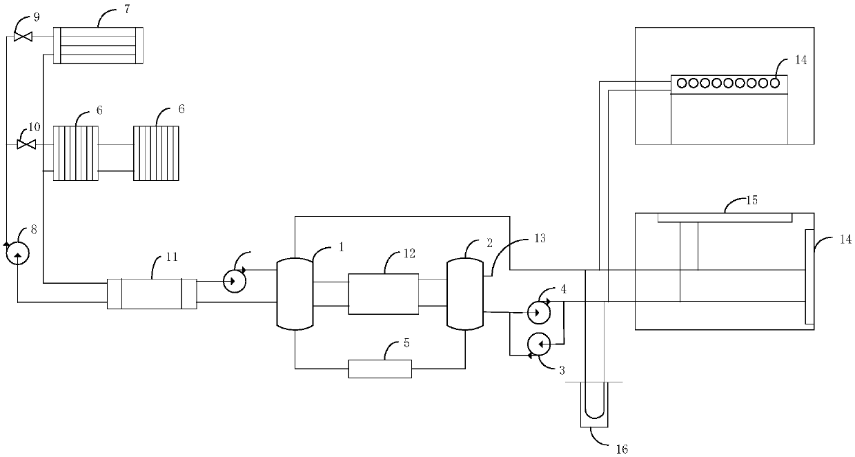
[0047] see figure 1 , figure 1 It is a schematic structural diagram of a renewable energy-based room temperature control system provided in Embodiment 1 of the present application.

[0048] Such as figure 1 As shown, the room temperature control system based on renewable energy provided in this embodiment includes:

[0049] Heat collection system, energy supply system, heat exchanger 11, controller, room temperature acquisition device;

[0050] The heat collection system utilizes air heat energy and solar heat collection;

[0051] The energy supply system includes a first water tank 1, a second water tank 2, a first circulating water pump 3, a second circulating water pump 4 and an indoor heat transfer device;

[0052] The heat collection system transfers heat to the first water tank through the heat exchanger;

[0053]The controller is respectively connected with the room temperature acquisition device, the first circulating water pump, and the second circulating water p...

Embodiment 2

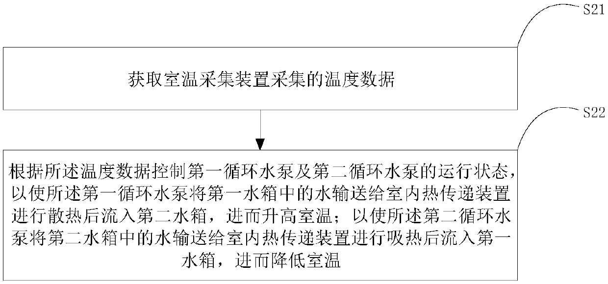
[0092] see figure 2 , figure 2 It is a schematic flowchart of a renewable energy-based room temperature control method provided in Embodiment 2 of the present application.

[0093] Such as figure 2 As shown, the renewable energy-based room temperature control method provided in this embodiment includes:

[0094] Step S21, acquiring the temperature data collected by the room temperature collection device;

[0095] Step S22: Control the operating states of the first circulating water pump and the second circulating water pump according to the temperature data, so that the first circulating water pump transfers the water in the first water tank to the indoor heat transfer device for heat dissipation and then flows into the second water tank , and then increase the room temperature; so that the second circulating water pump transports the water in the second water tank to the indoor heat transfer device to absorb heat and then flows into the first water tank, thereby lowerin...


PUM


Abstract

The invention relates to a renewable energy source-based room temperature control method and system. The system comprises a heat collecting system, an energy supplying system, a heat exchanger, a controller and a room temperature collecting device. The energy supplying system comprises a first water tank, a second water tank, a first circulating water pump, a second circulating water pump and an indoor heat transfer device. The heat collecting system transfers heat to the first water tank through the heat exchanger; the controller is connected to the room temperature collecting device, the first circulating water pump and the second circulating water pump; the first circulating water pump is used for conveying water in the first water tank to the indoor heat transfer device to be dissipated and flow into the second water tank; the second circulating water pump is used for conveying water in the second water tank to the indoor heat transfer device to absorb heat and flow into the firstwater tank; and the first water tank and the second water tank communicate through a water flow control device. In the room temperature raising process, a relatively high temperature is available forsupplied water, while in the room temperature reducing process, a relatively low temperature is available for the supplied water, so that the supplied water has a relatively excellent quality.

Description

technical field [0001] The present application relates to the technical field of renewable energy utilization, in particular to a method and system for controlling room temperature based on renewable energy. Background technique [0002] At present, the rural heating in winter mainly uses electricity, natural gas, and coal as energy sources, and heats the water circulating in the heating to achieve the purpose of raising the indoor temperature. For some houses with large indoor space and many rooms, the demand for water is large, and the return route is long. Generally, a circulating water pump and a water tank are used to cooperate with each other to circulate water between the heater and the water tank. When the circulating water pump is running, it will pump the water in the water tank into the heating in the room, the heat of the water will be continuously transferred out, and finally flow into the water tank. During this process, the supply and return water are mixed i...

Claims


Application Information

Patent Timeline
Patent Type & Authority Applications(China)
IPC IPC(8): F24D3/02F24D19/10F24S20/40F24H4/02
CPCF24D3/02F24D19/1006F24H4/02Y02B30/12
Inventor 韩中合吴迪刘志坚张玉龙王巧梅李鹏韩旭
Owner NORTH CHINA ELECTRIC POWER UNIV (BAODING)
Why Eureka
Try Eureka