Reconstructing method and system of reflector antenna far-field pattern

A technology for reconstructing systems and directional diagrams, applied to antenna radiation diagrams, complex mathematical operations, etc., can solve problems such as long calculation time, short calculation time, and consumption of several or even dozens of hours

Active Publication Date: 2019-04-12
XINJIANG ASTRONOMICAL OBSERVATORY CHINESE ACADEMY OF SCI
View PDF14 Cites 8 Cited by
  • Summary
  • Abstract
  • Description
  • Claims
  • Application Information

AI Technical Summary

Problems solved by technology

For large-aperture antennas, when working at low frequencies, such as the L-band (wavelength 18 cm), the radiation integral calculation is performed through numerical calculations. After the reflective surface is meshed (the grid size is related to the wavelength), the number of integral points Relatively few, the calculation time is short; however, for high-frequency work, such as Q-band (wavelength 7mm), the number of integration points is relatively large, and the calculation time will be

Method used


Image

  • Reconstructing method and system of reflector antenna far-field pattern
  • Reconstructing method and system of reflector antenna far-field pattern
  • Reconstructing method and system of reflector antenna far-field pattern

Examples


Embodiment 1

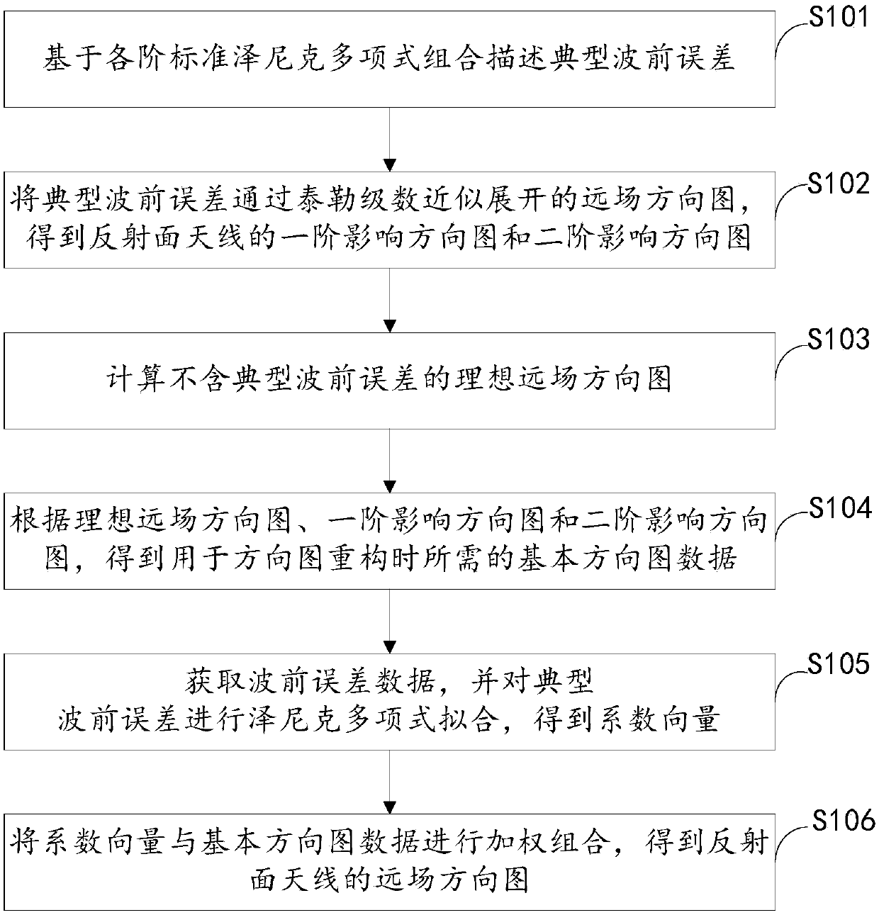
[0076] figure 1 It is a flow chart of the method for reconstructing the far-field pattern of the reflector antenna provided by Embodiment 1 of the present invention.

[0077] refer to figure 1 , the method includes the following steps:

[0078] Step S101, describing typical wavefront errors based on combinations of standard Zernike polynomials of each order;

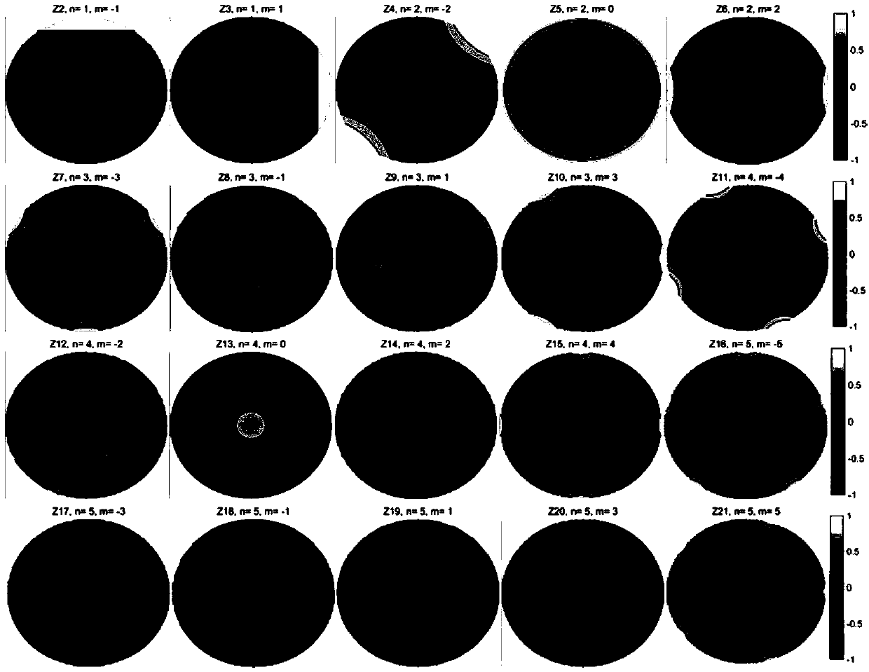
[0079] Specifically, for a parabolic antenna, its aperture surface is generally a circular surface, and the wavefront error of the aperture surface can be described by using Zernike circular polynomials. Zernike polynomials are a series of polynomials composed of trigonometric functions and radial functions. The polynomials are orthogonal in the circular domain, so the wavefront error of any shape can be represented by the linear combination of the terms. In addition, the wavefront error described by the Zernike polynomial can correspond to the traditional optical system aberration, which is widely used in astronomica...

Embodiment 2

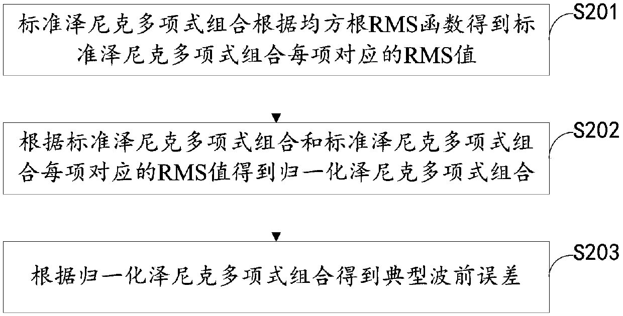
[0218] Such as Figure 8 As shown, the typical wavefront error is described based on the combination of standard Zernike polynomials of each order, and the first-order integral of the error pattern approximation and the first-order integral of the error pattern approximation are obtained according to the typical wavefront error, and then the approximate data of the first-order error pattern are obtained Approximate data with the first-order error pattern, that is, the first-order influence pattern and the second-order influence pattern of the reflector antenna in Embodiment 1; according to the geometric parameters and the geometrical optics radiation integral of the reflector antenna, the calculated The ideal far-field pattern data of the previous error; the ideal far-field pattern data, the approximate data of the first-order error pattern and the approximate data of the first-order error pattern constitute the basic pattern data; obtain the wavefront error data, and analyze t...

Embodiment 3

[0220] Figure 9 A schematic diagram of a system for reconstructing the far-field pattern of the reflector antenna provided in Embodiment 3 of the present invention.

[0221] refer to Figure 9 , the system consists of:

[0222] The description unit 10 is used to describe typical wavefront errors by combinations of standard Zernike polynomials of various orders;

[0223] The first acquisition unit 20 is used to obtain the first-order influence pattern and the second-order influence pattern of the reflector antenna by approximating the far-field pattern developed by the typical wavefront error through the Taylor series;

[0224] A calculation unit 30, configured to calculate an ideal far-field pattern without typical wavefront errors;

[0225] The second acquisition unit 40 is configured to obtain the basic pattern data required for pattern reconstruction according to the ideal far-field pattern, the first-order influence pattern and the second-order influence pattern;

[0...


PUM


Abstract

The invention provides a reconstructing method and system of a reflector antenna far-field pattern. The reconstructing method comprises the steps: the typical wavefront error is described based on standard Zernike polynomial combinations of all orders; according to the typical wavefront error, a first-order influence direction pattern and a second-order influence direction pattern of a reflector antenna are obtained through a far-field pattern with the approximately developed Taylor series; an ideal far-field pattern containing no typical wavefront error is calculated, and basic direction pattern data are obtained according to the ideal far-field pattern, the first-order influence direction pattern and the second-order influence direction pattern; wavefront error data are obtained, the typical wavefront error is subjected to Zernike polynomial fitting, and the coefficient vector is obtained; and weighted combination is conducted through the coefficient vector and the basic direction pattern data, and the reflector antenna far-field pattern is obtained. The calculation time can be reduced, and the reflector antenna far-field pattern can be quickly reconstructed.

Description

technical field [0001] The invention relates to the technical field of antenna measurement, in particular to a reconstruction method and system for the far-field pattern of a reflector antenna. Background technique [0002] Reflector antenna is a typical electromechanical integrated electronic equipment. With the continuous development of radio and electronic technology, reflector antenna is widely used in microwave communication, military reconnaissance and radio astronomy and other fields. In recent years, the research on radio astronomy has continued to deepen. As an important astronomical observation tool, reflector antennas have developed towards high-frequency bands, high gain and large receiving area. my country has built the world's largest 500m spherical reflector radio telescope in Guizhou. At the same time, the world's largest caliber 110m fully movable radio telescope (QiTai radio Telescope, referred to as QTT) is being built in Xinjiang, which will be mainly used...

Claims


Application Information

Patent Timeline
IPC IPC(8): G01R29/10G06F17/17
CPCG01R29/10G06F17/17
Inventor 项斌斌王娜王从思林上民连培园王伟薛飞
Owner XINJIANG ASTRONOMICAL OBSERVATORY CHINESE ACADEMY OF SCI
Why Eureka
Try Eureka