
Outer rotor flux switching motor with high permanent-magnet utilization rate

A technology of magnetic flux switching motors and outer rotors, applied in the direction of magnetic circuit rotating parts, magnetic circuits, electric components, etc., can solve the problem of increased self-inductance of armature windings, magnetic flux leakage from the outer circle of motor stators, and low utilization of permanent magnets in motors To achieve the effect of increasing the magnetic flux density and power, increasing the magnetic potential of the magnetic circuit, and improving the utilization rate of the permanent magnet

Active Publication Date: 2019-04-12
JIANGSU UNIV
View PDF2 Cites 4 Cited by
  • Summary
  • Abstract
  • Description
  • Claims
  • Application Information

AI Technical Summary

Problems solved by technology

[0003] Chinese patent application number 200910184947.1 discloses a multi-tooth fault-tolerant permanent magnet flux switching motor. The stator teeth of the motor have a slotted structure, which increases the self-inductance of the armature winding of the motor and enhances the ability to suppress short-circuit current. The positioning torque of the motor is reduced, but the spoke-type permanent magnets placed on the stator lead to unavoidable magnetic flux leakage on the outer circle of the motor stator, which makes the permanent magnet utilization of the motor lower
Chinese Patent Application No. 201020652579.7 discloses a double salient pole motor with magnetic flux switching of the outer rotor. The rotor of the motor is external, and the space between the motor stator and the shaft is small, which reduces the magnetic flux leakage of the motor to a certain extent, thereby improving The beneficial effect of permanent magnet utilization, however, the alternating tangentially magnetized permanent magnets on the motor stator bring about the inevitable shaft flux leakage

Method used


Image

  • Outer rotor flux switching motor with high permanent-magnet utilization rate
  • Outer rotor flux switching motor with high permanent-magnet utilization rate
  • Outer rotor flux switching motor with high permanent-magnet utilization rate

Examples


Embodiment Construction

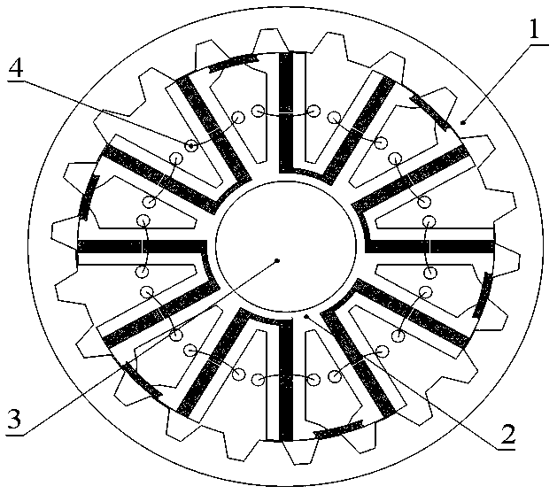
[0027] see figure 1 , the present invention includes a rotor 1 , a stator 2 , a shaft 3 and a concentrated winding 4 . The stator 2 is coaxially located inside the rotor 1 , and the center of the stator 2 is used to place the rotating shaft 3 . There is an air gap between the inner wall of rotor 1 and the outer wall of stator 2. The thickness of the air gap is related to the power level of the motor, the selected permanent magnet material, and the processing and assembly process of rotor 1 and stator 2. Both rotor 1 and stator 2 have a thickness of 0.35 It is made of laminated silicon steel sheets with a thickness of mm, and the lamination coefficient is 0.95.

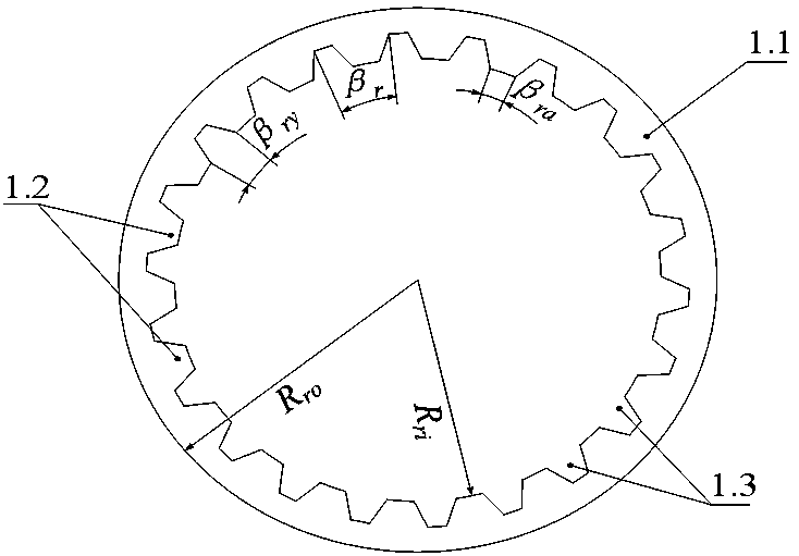
[0028] see figure 2 , the rotor 1 belongs to the salient pole structure in structure, and there is neither permanent magnet nor winding on the rotor 1. Rotor 1 consists of rotor yoke 1.1, N r Composed of a rotor salient pole 1.2 and a rotor slot 1.3, N r The rotor salient poles 1.2 are evenly distributed on th...


PUM


Abstract

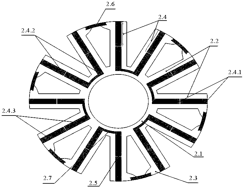
The invention discloses an outer rotor flux switching motor with high permanent-magnet utilization rate. A stator is coaxially arranged in a rotor, the stator comprises a magnetic conduction ring andN<s> V-shaped stator salient poles, wherein segmented permanent-magnet steel is fixedly embedded between two adjacent V-shaped stator salient poles, each segmented permanent-magnet steel is divided into N segments of magnetic steel along a radial direction of the stator, a magnetic conduction bridge is arranged between adjacent two segments of magnetic steel of the N segments of magnetic steel, each segment of magnetic steel is of the same Halbach array structure, a boot part facing a stator groove is arranged at an outer end part per one of the V-shaped stator salient poles, boot part permanent-magnet steel is fixedly embedded between the two boot parts of the same V-shaped stator salient pole, arc-shaped inner-end permanent magnetic steel is arranged at an inner end of the V-shaped stator salient pole which is not provided with the boot part, and inner ends of adjacent two segmented permanent-magnet steel are connected by the inner-end permanent-magnet steel. By the outer rotor fluxswitching motor, leakage flux to two ends of the permanent-magnet steel segmented along the radial direction of the stator is effectively reduced, and the effect of improving the permanent-magnet utilization ratio of the motor is obtained.

Description

technical field [0001] The invention belongs to the technical field of motor manufacturing, in particular to a permanent magnet motor suitable for electric vehicles and the like requiring high torque density and high permanent magnet utilization. Background technique [0002] Flux switching motors have shown potential application prospects in the fields of electric vehicles, wind power generation, and aerospace because of their advantages such as simple rotor structure, easy heat dissipation, and high torque output capacity. However, due to the special stator structure of the traditional flux switching motor, there are many problems such as low permanent magnet utilization rate caused by more flux leakage in the outer circle of the stator. Therefore, how to improve the utilization of permanent magnets has become a difficult problem in the field of flux switching motor design. [0003] Chinese patent application number 200910184947.1 discloses a multi-tooth fault-tolerant pe...

Claims


Application Information

Patent Timeline
IPC IPC(8): H02K1/14H02K1/17H02K1/24
CPCH02K1/14H02K1/17H02K1/24H02K2201/03H02K2213/03
Inventor 朱孝勇蒋敏项子旋全力陈文汝
Owner JIANGSU UNIV
Learn More