Weft insertion device for air-jet loom and automatic adjusting method of weft insertion device

A weft insertion device and air-jet loom technology, which is applied in looms, textiles, textiles and papermaking, etc., can solve the problems of difficult weft yarn arrival, time deviation of weft and weft yarn arrival, less compressed air consumption, etc., and achieve the goal of reducing labor. Effect

Pending Publication Date: 2019-04-16
SHANDONG RIFA TEXTILE MACHINERY
View PDF3 Cites 3 Cited by
  • Summary
  • Abstract
  • Description
  • Claims
  • Application Information

AI Technical Summary

Problems solved by technology

This is the most common, but the problem with such a setting is that it is difficult to achieve the best weft insertion, that is, it is difficult to achieve stable weft arrival and minimum compressed air consumption
The defect is that if the injection start time does not follow the adjustment, it may not only make the weft insertion fail to reach a stable state, but also cause waste of compressed air
This method uses the difference between the arrival time of a single weft yarn and the target arrival time to correct the opening/closing timing of the next weft electromagnetic valve, which is easy to make the special situation such as weft knots, thickness, fluff, reed friction, warp hairiness blocking, etc. The large sudden fluctua

Method used


Image

  • Weft insertion device for air-jet loom and automatic adjusting method of weft insertion device
  • Weft insertion device for air-jet loom and automatic adjusting method of weft insertion device
  • Weft insertion device for air-jet loom and automatic adjusting method of weft insertion device

Examples


Embodiment Construction

[0040] Embodiments of the present invention are described below with reference to the accompanying drawings.

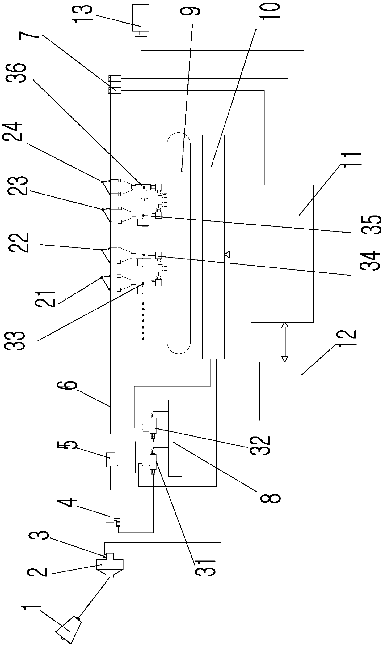
[0041] combine Figure 1 to Figure 7 , a weft insertion device for an air-jet loom, comprising a weft feeder 2, a yarn retaining needle 3, an auxiliary main nozzle 4, a swinging main nozzle, a weft detection detector 7, a main air bag 8, an auxiliary air bag 9, and a solenoid valve control device 10. Main control computer 11, display input device 12, encoder 13, auxiliary nozzles 21-24, auxiliary injection solenoid valves 31-36, multiple auxiliary nozzles 21-24 form an auxiliary nozzle group,

[0042] The main control computer 11 is electrically connected with the electromagnetic valve control device 10, the display input device 12, the encoder 13, and the weft detection detector 7 respectively, and the electromagnetic valve control device 10 is respectively connected with the yarn retaining needle 3, the electromagnetic valve 31, the electromagnetic valve Two 32, th...


PUM


Abstract

The invention discloses a weft insertion device for an air-jet loom and an automatic adjusting method of the weft insertion device. The weft insertion device comprises a yarn stopping needle, an auxiliary main nozzle, a swing main nozzle, a weft detector, a main air bag, an auxiliary air bag, an electromagnetic valve control device, a main control computer, a display input device, an encoder, auxiliary nozzles and auxiliary spraying electromagnetic valves, wherein the auxiliary nozzles form an auxiliary nozzle group; the main control computer is electrically connected with the electromagneticvalve control device, the display input device, the encoder and the weft detector; the electromagnetic valve control device is in electrical signal connection with the yarn stopping needle, a first electromagnetic valve, a second electromagnetic valve and the auxiliary spraying electromagnetic valves; the auxiliary main nozzle is connected with the main air bag through the first electromagnetic valve; the swing main nozzle is connected with the main air bag through the second electromagnetic valve; the auxiliary nozzles are connected with the auxiliary air bag through the auxiliary spraying electromagnetic valves respectively. The jet starting time and the jet ending time of the auxiliary nozzles can be dynamically adjusted, the jet compressed air is minimized, weft insertion is stably conducted, and the labor amount of an operator is reduced.

Description

technical field [0001] The invention relates to the technical field of air-jet looms, in particular to a weft insertion device of an air-jet loom and an automatic adjustment method thereof, which can dynamically adjust the start and end timings of injection of auxiliary nozzles. Background technique [0002] The air-jet loom uses compressed air sprayed from the main nozzle and the auxiliary nozzle for weft insertion. In the prior art, the spraying angles of the main nozzle and the auxiliary nozzle are artificially set in advance according to experience, and then modified according to the weaving condition. This is the most common, but the problem with such a setting is that it is difficult to achieve the best weft insertion, that is, it is difficult to achieve stable weft yarn arrival and minimum compressed air consumption. [0003] Reference document 1, patent document CN 102534953 A, provides a method for setting the injection period of sub-nozzles of an air-jet loom, whi...

Claims


Application Information

Patent Timeline
IPC IPC(8): D03D47/30
CPCD03D47/304D03D47/3053D03D47/3073
Inventor 高超吉学齐陶广川
Owner SHANDONG RIFA TEXTILE MACHINERY
Why Eureka
Try Eureka