Vibration monitoring system and method based on dual fiber grating array

A vibration monitoring system, dual fiber grating technology, applied in measuring devices, measuring ultrasonic/sonic/infrasonic waves, instruments, etc., can solve problems such as phase noise increase, signal vibration cancellation, signal-to-noise ratio deterioration, etc., to reduce signal distortion , Improve the system signal-to-noise ratio and avoid phase noise

Active Publication Date: 2020-11-24
WUHAN UNIV OF TECH
View PDF13 Cites 0 Cited by
  • Summary
  • Abstract
  • Description
  • Claims
  • Application Information

AI Technical Summary

Problems solved by technology

However, in practical applications, since the change of the length of each small section of the fiber will cause the phase change of the interference signal, the final phase change is the accumulation of the length changes of the entire section of the fiber between the gratings. When the vibration wave signal is transmitted to the fiber At each point of , the response at that point is delayed with distance, so there is a possibility of vibration cancellation in the detected signal
As the length of the fiber increases, the impact of external noise on the length of the fiber is far greater than the impact of the vibration source, resulting in the deterioration of the signal-to-noise ratio of the system
The phase noise introduced by the frequency instability of the light source also increases with the length of the fiber
In order to avoid the occurrence of the above situation, the interval between the gratings can be reduced, but this method will be limited by hardware circuits such as the pulse width of the pulse signal, the bandwidth of the hardware circuit, the sampling rate of signal acquisition, and the rate of data transmission.

Method used


Image

  • Vibration monitoring system and method based on dual fiber grating array
  • Vibration monitoring system and method based on dual fiber grating array
  • Vibration monitoring system and method based on dual fiber grating array

Examples


Embodiment Construction

[0023] Below in conjunction with specific embodiment the present invention is described in further detail:

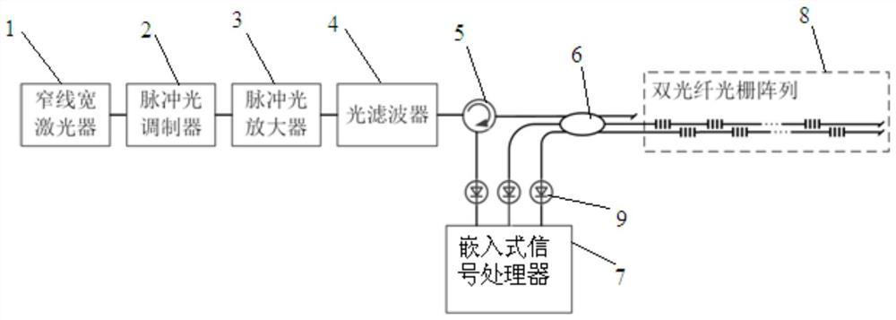
[0024] A vibration monitoring system based on dual fiber grating arrays designed by the present invention, such as figure 1 As shown, it includes a narrow linewidth laser 1, a pulsed light modulator 2, a pulsed light amplifier 3, an optical filter 4, a circulator 5, a coupler 6, an embedded signal processor 7 and a double fiber grating array 8, wherein, The continuous optical signal output end of the narrow linewidth laser 1 is connected to the input end of the pulsed optical modulator 2, the pulsed optical signal output end of the pulsed optical modulator 2 is connected to the input end of the pulsed optical amplifier 3, and the output end of the pulsed optical amplifier 3 is connected to the optical The input end of the filter 4, the output end of the optical filter 4 are connected to the first communication end of the circulator 5, the second communication end of the...


PUM


Abstract

The invention relates to a vibration monitoring system based on a double fiber grating array, which is characterized in that a narrow linewidth laser, a pulse light modulator, a pulse light amplifierand an optical filter are connected in order, an output terminal of the optical fiber is connected with a first communication terminal of a circulator, a second communication terminal of the circulator is connected with a front first communication terminal of a coupler, a back first communication terminal of the coupler is knotted and out of service, a third communication terminal of the circulator is connected with a first signal input terminal of an embedded signal processor, a front second communication terminal of the coupler is connected with a second signal input terminal of the embeddedsignal processor, a front third communication terminal of the coupler is connected with a third signal input terminal of the embedded signal processor, a back second communication terminal of the coupler is connected with a first optical fiber of the double fiber grating array, and a back third communication terminal of the coupler is connected with a second optical fiber of the double fiber grating array. The vibration monitoring system can restore vibration signals more authentically without increasing the hardware cost.

Description

technical field [0001] The invention relates to the technical field of fiber grating sensing, in particular to a vibration monitoring system and method based on a double fiber grating array. Background technique [0002] With the development of vibration sensor monitoring technology, high-precision and high-sensitivity test requirements for vibration signal monitoring in engineering have been continuously put forward. Long-term monitoring of vibration signals has become one of the goals of the engineering community. Research and development of high-performance vibration Monitoring systems are imperative. The emergence of fiber grating sensing technology coincides with the needs of vibration monitoring technology. Compared with traditional mechanical, piezoelectric, magnetoelectric and other sensors, fiber grating sensors have small size, light weight, good flexibility, With a series of advantages such as strong anti-electromagnetic interference ability, high precision and w...

Claims


Application Information

Patent Timeline
Patent Type & Authority Patents(China)
IPC IPC(8): G01H9/00
CPCG01H9/004
Inventor 李政颖王加琪王洪海刘佳佩王立新姜德生
Owner WUHAN UNIV OF TECH
Why Eureka
Try Eureka