Out-of-focus low-sensitivity and process window enhancement light source-mask batch optimization method

A technology of process window and optimization method, which is applied in the field of integrated circuit design and lithography resolution enhancement, and can solve problems such as difficulty in directly improving uniformity and consistency, limited ability to compensate defocus error, and low robustness of focus shift , achieve good optimization effect and optimization efficiency, relax error tolerance, and improve the effect of process window

Active Publication Date: 2019-04-16
BEIJING INSTITUTE OF TECHNOLOGYGY
View PDF5 Cites 8 Cited by
  • Summary
  • Abstract
  • Description
  • Claims
  • Application Information

AI Technical Summary

Problems solved by technology

[0005] However, the above optimization methods are difficult to directly improve the uniformity and consistency of exposure patterns under different defocus planes, so the ability to compensate for defocus errors is limited, and the robustness of the optimization system to focus shift is relatively low
At the same time, the above method is optimized by gradient descent (GD for short) or stochastic gradient descent (SGD for short). For a large-scale, large-scale defocused training set, the global search ability of this method is limited. Restricted, optimized performance is weak

Method used


Image

  • Out-of-focus low-sensitivity and process window enhancement light source-mask batch optimization method
  • Out-of-focus low-sensitivity and process window enhancement light source-mask batch optimization method
  • Out-of-focus low-sensitivity and process window enhancement light source-mask batch optimization method

Examples


Embodiment 1

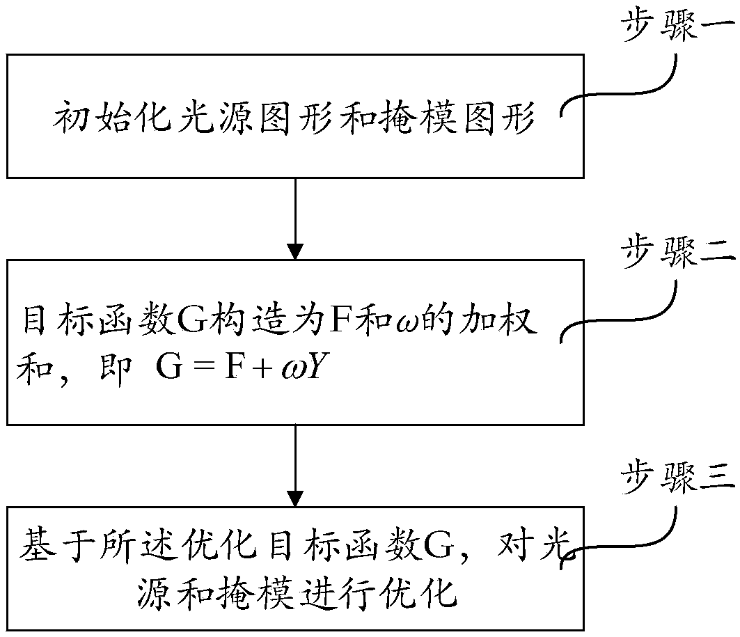
[0039] Such as figure 1 As shown, a light source-mask batch optimization method with low defocus sensitivity and enhanced process window, the specific process is:

[0040] Step 1. Initialize the light source pattern and mask pattern;

[0041] Step 2, constructing the optimization objective function G:

[0042] Let F be the imaging fidelity function, which is defined as the square of the Euler distance between the image in the photoresist corresponding to the target pattern and the current light source pattern and mask pattern, that is in is the target photoresist pattern, Z(β i ) represents the defocus amount β of the photoresist corresponding to the current light source pattern and mask pattern calculated by the vector imaging model i Imaging at time; where, β i is a random defocus variable that obeys a uniform distribution, is the mathematical expectation, Represents the binorm of a matrix.

[0043] The penalty function of the sensitivity term of the imaging resu...

Embodiment 2

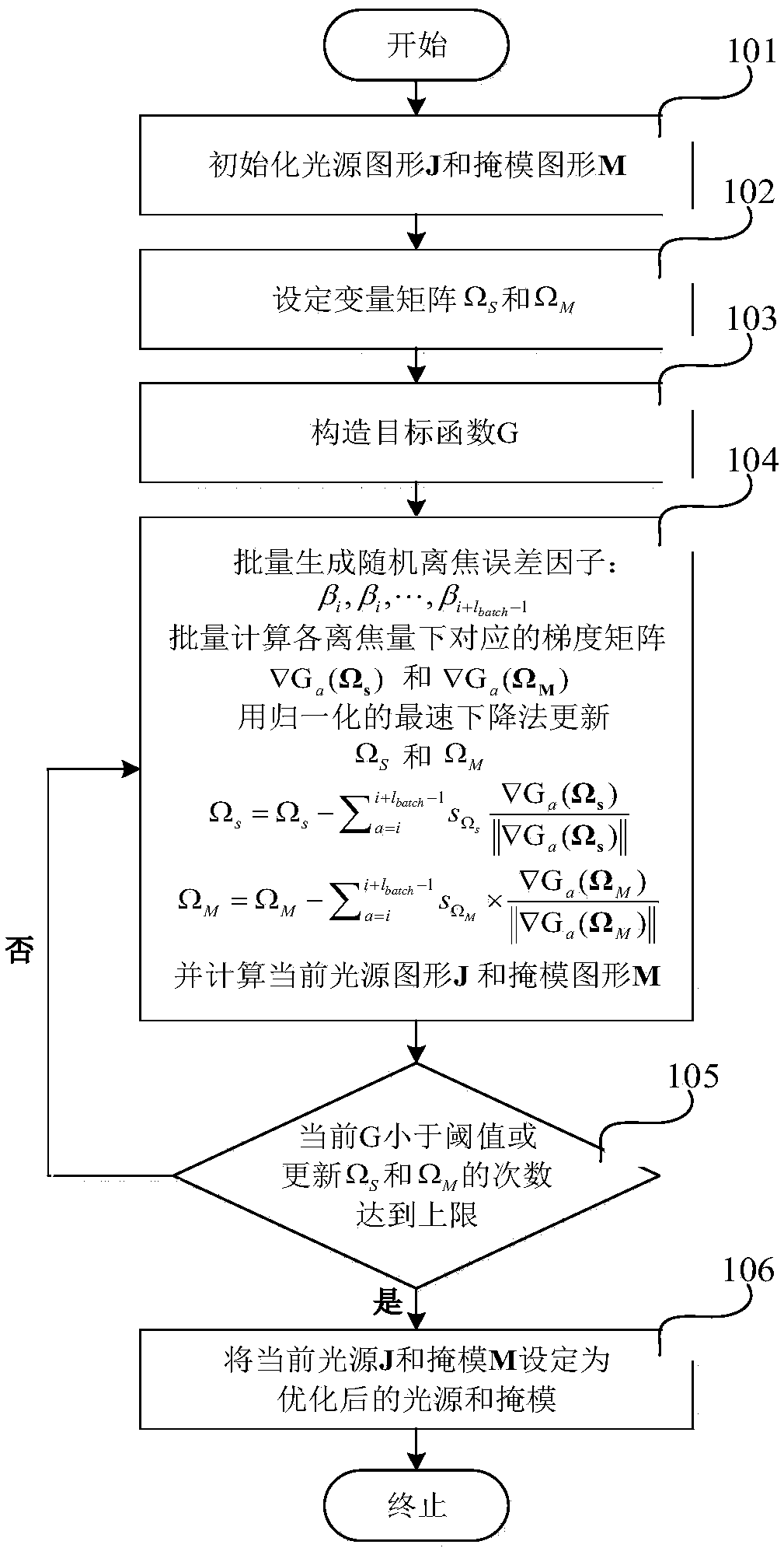
[0048] Such as figure 2 As shown, this embodiment establishes a multi-target light source-mask batch optimization method for low sensitivity to defocus, and the specific steps are:

[0049] (1), initialize the size of the light source to N S ×N S The light source pattern J, the mask pattern M is initialized to a target pattern with a size of N×N where N S and N are integers.

[0050] (2), set the pixel value of the luminous area on the initial light source graphic J to 1, and the pixel value of the non-luminous area to 0; set the size to N S ×N S The light source variable matrix Ω s : When J(x s ,y s )=1, When J(x s ,y s )=0, where J(x s ,y s ) represents each pixel on the light source graph (x s ,y s ) pixel value; set the transmittance of the initial mask pattern M to 1 in the light-transmitting area, and 0 in the light-blocking area; set the mask variable matrix Ω with a size of N×N M : When M(x,y)=1, When M(x,y)=0, Among them, M(x, y) represents th...

Embodiment

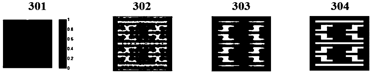
[0095] Such as image 3 Optimized light source patterns, mask patterns and their corresponding photoresist in defocused conditions for related technologies (CN 102692814 B, 2013.09.11) (hereinafter referred to as initial SMO) (optimization is only performed under nominal photolithography conditions) picture. Shown is a schematic of the initial light source, the initial mask and its corresponding imaging in the photoresist. exist image 3 Among them, 301 is an optimized light source pattern, and different colors represent different normalized intensity distributions of the light source. 302 is the optimized mask pattern, which is also the target pattern, white represents the light-transmitting area, black represents the light-blocking area, and its characteristic size is 45nm. In the case of a defocus of 90nm, 303 is an image formed in the photoresist by the photolithography system after using 301 as a light source and 302 as a mask. Comparing the target exposure pattern 30...


PUM

PropertyMeasurementUnit
optical propertiesaaaaaaaaaa

Abstract

The invention provides an out-of-focus low-sensitivity and process window enhancement light source-mask batch optimization method. The process comprises the following steps: selecting an initial lightsource and a mask graph; establishing an out-of-focus high-fidelity objective function as a square of an Euler distance between a target graph and an image in the photoresist corresponding to a current light source graph and the mask graph; constructing an out-of-focus low-sensitivity penalty function item (shown in the specification), wherein Idefox ((beta)i) is a spatial image calculated through a vector imaging model at the position of an out-of-focus error (beta)i, and (beta)I is a random out-of-focus variable obeying uniform distribution; respectively calculating weighted analysis gradients delta(G) of the objective function and a penalty function, namely delta(G) = F + Y; and updating and optimizing a light source and a mask through a small-batch gradient descent method. According to the system optimized through the method, the exposure graph which is more uniform and consistent is obtained within a certain defocusing error range, and the exposure graph is more uniform and consistent. Compared with a traditional light source-mask optimization method, the method has the advantages of higher defocusing robustness, larger focal depth and larger process window.

Description

technical field [0001] The invention relates to a light source-mask batch optimization method with low defocus sensitivity and enhanced process window, belonging to the technical fields of integrated circuit design and lithographic resolution enhancement. Background technique [0002] Photolithography is the core process in the VLSI manufacturing field. At present, the operating wavelength of the mainstream photolithography system in the industry is 193nm. As the technology node moves down, resolution enhancement technology must be introduced to improve the imaging quality of lithography. Traditional resolution enhancement technologies such as source mask optimization (SMO) can correct the optical proximity effect (OPE) and exposure process errors by optimizing the exposure light source and mask pattern. Imaging distortion, graphics offset, image quality degradation and other issues. [0003] However, the traditional ideal lithography SMO, such as the prior art (CN 102692...

Claims


Application Information

Patent Timeline
Patent Type & Authority Applications(China)
IPC IPC(8): G03F7/20
CPCG03F7/70066G03F7/70125G03F7/70425G03F7/70433G03F7/70483G03F7/705G03F7/70508
Inventor 李艳秋韦鹏志李铁
Owner BEIJING INSTITUTE OF TECHNOLOGYGY
Why Eureka
Try Eureka