Hydraulic units for the degassing of hydraulic oils and for their dehydration

A hydraulic mechanism and hydraulic oil technology, applied in liquid degassing, liquid degassing adjustment/control, mechanical equipment, etc., can solve problems such as surface corrosion, affecting filterability, and accelerated aging

Active Publication Date: 2021-07-09
ROBERT BOSCH GMBH
View PDF6 Cites 0 Cited by
  • Summary
  • Abstract
  • Description
  • Claims
  • Application Information

AI Technical Summary

Problems solved by technology

Water accelerates the oxidation-induced aging of hydraulic oils, deteriorates the lubricating properties (Schmiereigenschaften), and affects the filterability of the oil (Filtrierbarkeit) due to hydrolytic breakdown and corrosion products, and it causes surface corrosion

Method used


Image

  • Hydraulic units for the degassing of hydraulic oils and for their dehydration
  • Hydraulic units for the degassing of hydraulic oils and for their dehydration
  • Hydraulic units for the degassing of hydraulic oils and for their dehydration

Examples


Embodiment Construction

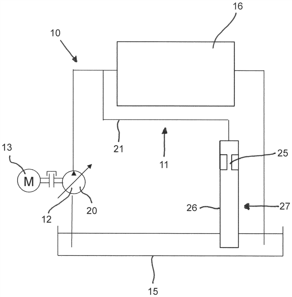
[0033] according to figure 1 The hydraulic equipment includes a hydraulic working circuit 10 and a hydraulic secondary circuit 11, which forms a mechanism for degassing and dehydrating. Belonging to the working circuit 10 is a hydrostatic main pump 12 in the form of a squeezer, which is adjustable in its displacement and which can be driven by a motor 13 , for example an internal combustion engine or an electric motor. If necessary, one or more hydraulic loads are supplied with hydraulic oil by a squeeze pump (Verdränger pump 12 ) via one or more hydraulic valves. The squeeze pump 12 pumps hydraulic oil from a tank 15 to the hydraulic load, into which hydraulic oil flows from the hydraulic load back.

[0034] hydraulic loads and hydraulic valves in figure 1 is shown in a very simplified manner and are collectively assigned the reference numeral 16 .

[0035] The hydraulic secondary circuit 11 is a separate high-pressure circuit and is used for degassing and dehydrating the ...


PUM


Abstract

According to the invention, a hydraulic unit for degassing and dehydrating hydraulic oil with a pressure source from which the liquid to be degassed flows through a throttling point, characterized in that the flow through said throttling point The amount of liquid is coordinated with the flow cross-section of the restriction, so that a cavitation or supercavitation is formed downstream of the restriction, and there is a device by which any Kind of air is introduced into the hydraulic oil.

Description

technical field [0001] The invention relates to a hydraulic unit for degassing and dehydrating hydraulic oil with a pressure source from which the liquid to be degassed flows through a throttling point. Background technique [0002] For various reasons, air contained in hydraulic fluids creates problems in hydraulic equipment. The higher the free or undissolved air fraction, the higher the undesired compressibility of the hydraulic oil itself. If the hydraulic fluid pumped by the pump also contains air bubbles, this leads to poor efficiency and high noise levels. The more free air in the hydraulic fluid, the faster the hydraulic fluid will age. Usually, attempts are made by designing the storage container to be of a large size so that air bubbles arising in the hydraulic system from the hydraulic oil located in the storage container rise and vent, wherein the residence time of the hydraulic pressure medium is correspondingly long. This process can take place relatively sl...

Claims


Application Information

Patent Timeline
Patent Type & Authority Patents(China)
IPC IPC(8): F15B21/044F15B21/041F15B1/26
CPCF15B1/26F15B21/044F15B2211/20546F15B2211/20576F15B2211/40507F15B2211/611B01D19/0063B01D19/0094F15B21/041
Inventor K.哈布尔H.梅林M.米勒
Owner ROBERT BOSCH GMBH
Why Eureka
Try Eureka