Wood carving device

A technology of wood and mounting boards, which is applied in the field of engraving machines, can solve the problems of engraving position deviation, bulky body, and difficulty in moving, and achieve the effect of easy maintenance and replacement, convenient installation and disassembly, and improved scope of application

Active Publication Date: 2019-04-19
安徽天盛家具有限公司
View PDF8 Cites 4 Cited by
  • Summary
  • Abstract
  • Description
  • Claims
  • Application Information

AI Technical Summary

Problems solved by technology

[0003] And wood engraving device is a kind of equipment that wood is carved, but most of existing wood engraving machines are integrated structure, and the body is bulky, and it is difficult to move and transport, and existing wood engraving machine is engraving wood When the wood is prone to shaking, the position of the carving will be deviated, which will affect the quality and effect of the carving, making it difficult to meet the needs of production

Method used


Image

  • Wood carving device
  • Wood carving device
  • Wood carving device

Examples


Embodiment 1

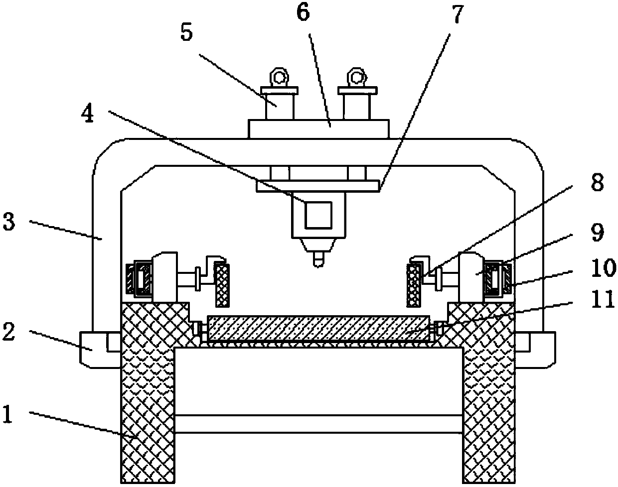
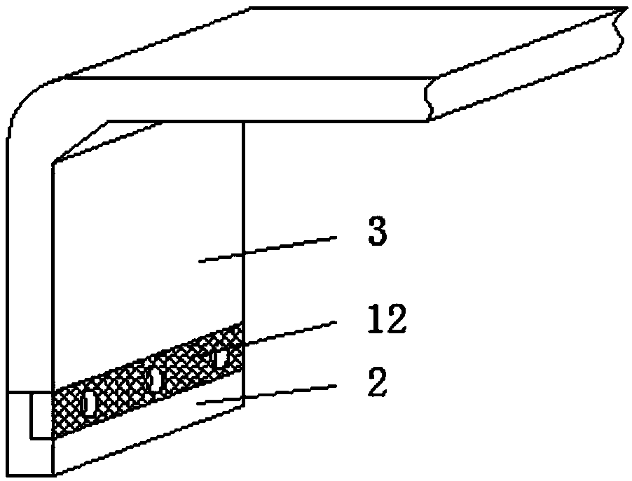
[0025] Embodiment 1, with reference to Figure 1-5 , a wood engraving device, comprising a main frame 1, a main frame 3 and an engraving device 4, the main frame 3 is located above the main frame 1, side mounting frames 2 are welded on both sides of the main frame 1, and the main frame 3 is an inverted U-shaped structure , the center of the upper surface of the horizontal end of the main frame 3 is provided with a mounting groove 21, and a mounting plate 6 is clamped on the top of the mounting groove 21 through an alignment card 20, and an electric push rod 5 is welded on the mounting plate 6, and the lower surface of the mounting plate 6 The edge is provided with an alignment card slot for use with the alignment card 20, and the mutual alignment between the alignment card 20 and the alignment card slot can make the position of the mounting plate 6 more accurate during installation without deviation. Thereby the position of the equipment installed on the mounting plate 6 is ac...

Embodiment 2

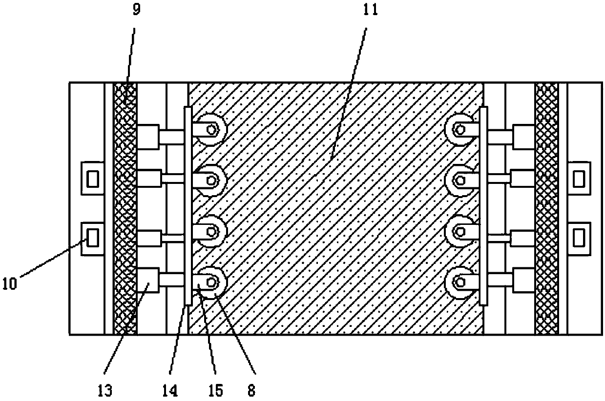
[0026] Embodiment 2, with reference to figure 1 , image 3 A conveyor belt 11 is laid on the center line of the upper surface of the main body support 1, and the upper surface of the main body support 1 is welded with a stand 9, and the inner side of the stand 9 is connected with a movable plate 14 through a limit sleeve rod 13, and the outer side of the stand 9 is fixed by bolts There is a hydraulic cylinder 10, the piston rod of the hydraulic cylinder 10 is welded to one side of the vertical frame 9 and the movable plate 14, and a plurality of roller frames 15 are welded equidistantly on the inner side of the movable plate 14, and the roller frame 15 is an L-shaped structure. The lower side of the horizontal end of the frame 15 is rotatably connected with a side anti-deviation roller shaft 8. There are two groups of side anti-deviation roller shafts 8, and the two groups of side anti-deviation roller shafts 8 are symmetrical to each other about the vertical center line of th...

Embodiment 3

[0027] Embodiment 3, with reference to figure 1 , Figure 3-5 , the upper surface of the main frame 3 is located at both sides of the mounting plate 6 and is provided with an installation chute 16, the inside of the installation chute 16 is connected with an adjustment bolt 18 through an elastic member 17, and one side of the adjustment bolt 18 is welded with a positioning pin 19, and the positioning pin One end of 19 runs through the outer wall of the mounting chute 16 and is pinned to the mounting plate 6. The two sides of the mounting plate 6 are provided with pin holes for use with the positioning pin 19. The setting of this structure makes the mounting plate 6 a detachable structure. Only need to slide the adjusting bolt 18 to make the elastic part 17 shrink, and the positioning pin 19 can be received inside the installation chute 16, so that the installation and disassembly of the device are convenient. The engraving device 4 below can be disassembled by dismounting the...


PUM


Abstract

The invention discloses a wood carving device. The wood carving device comprises a main support, a main rack and a carving device. The main rack is located above the main support. Side mounting racksare welded to the upper portions of the two sides of the main support. The main rack is of a U-shaped structure. Pin plates are welded to the lower portions of the two vertical ends of the main rack.The main rack is in mortise and tenon connection with the side mounting racks through the pin plates. A mounting groove is formed in the center of the upper surface of the horizontal end of the main rack. A mounting plate is clamped to the mounting groove through alignment clamps. Electric push rods are welded to the mounting plate. The bottoms of the electric push rods penetrate through the mounting plate and the main rack to be provided with a lifting plate in a welded mode. The carving device is fixed below the lifting plate through bolts. The wood carving device is suitable for wood carving. The position of wood is not prone to skewing in the carving process. The wood carving device can be applicable to wood with different widths and is convenient to install, dismantle and move.

Description

technical field [0001] The invention belongs to the technical field of engraving machines, in particular to a wood engraving device. Background technique [0002] Engraving is a combination of drilling and milling in terms of processing principle. The various data input modes of the engraving machine are easy to handle according to the needs. There are two types of computer engraving machines: laser engraving and mechanical engraving. These two types have high power and low power. Because the engraving machine has a wide range of applications, it is necessary to understand the most suitable application range of various engraving machines. The low-power ones are only suitable for double-color plates, architectural models, small signs, three-dimensional crafts, etc., while engraving jade, metal, etc. need The power is above 1500W, the high-power engraving machine can do the things of the low-power engraving machine, and it is most suitable for large-scale cutting, embossing an...

Claims


Application Information

Patent Timeline
Patent Type & Authority Applications(China)
IPC IPC(8): B44B1/00B44B1/06B44B3/00B44B3/06
CPCB44B1/00B44B1/06B44B3/005B44B3/06B44B2700/02B44B2700/04B44B2700/12
Inventor 焦家臣
Owner 安徽天盛家具有限公司
Why Eureka
Try Eureka