Leakage plate of 7.5 micrometer electronic yarn drawing equipment

An electronic yarn and wire drawing technology, applied in glass manufacturing equipment, manufacturing tools, etc., can solve the problems of high production cost, fewer leakage plate partitions, low production efficiency, etc. Effect

Pending Publication Date: 2019-04-19
LINZHOU GUANGYUAN NEW MATERIAL TECH
View PDF7 Cites 4 Cited by
  • Summary
  • Abstract
  • Description
  • Claims
  • Application Information

AI Technical Summary

Problems solved by technology

[0002] The existing E225 drain plate is mainly 1200H, that is, six partitions, and there are fewer partitions, resulting in low glass liquid flow per unit time and low efficiency
The thickness of the six-point drawing electrode and the aperture of the leak nozzle should not be set at a high temperature, which cannot meet the requirements of the high-speed wire drawing process
During the use of the six-point leak board, the temperature of the leak nozzle in the periphery of the single area is lower than that of other areas, and the tension is too high compared with other areas, which may cause flying wires, hairiness and other quality abnormalities
[0004] 1. Liufenla E225-1200H has fewer partitions, low production efficiency, high unit production cost, and insufficient market competitiveness;
[0005] 2. It is not suitable to set a higher temperature for the thickness of the electrode and the aperture of the leak nozzle, which cannot meet the requirements of the high-speed production process;
[0006] 3. The aperture is small, and the flow rate per unit time is low, which cannot meet the requirements of high-speed production technology;
[0007] 4. The leakage nozzle of the periphery of a single partition is lower than that of other regions, and the tension is too large compared with other regions, which may cause flying silk, hairiness and other quality abnormalities

Method used


Image

  • Leakage plate of 7.5 micrometer electronic yarn drawing equipment
  • Leakage plate of 7.5 micrometer electronic yarn drawing equipment
  • Leakage plate of 7.5 micrometer electronic yarn drawing equipment

Examples


Embodiment 1

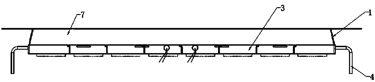
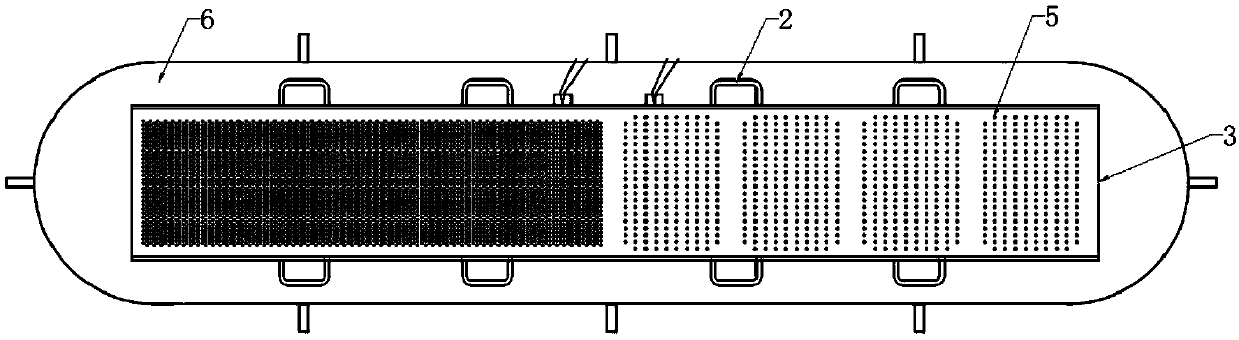
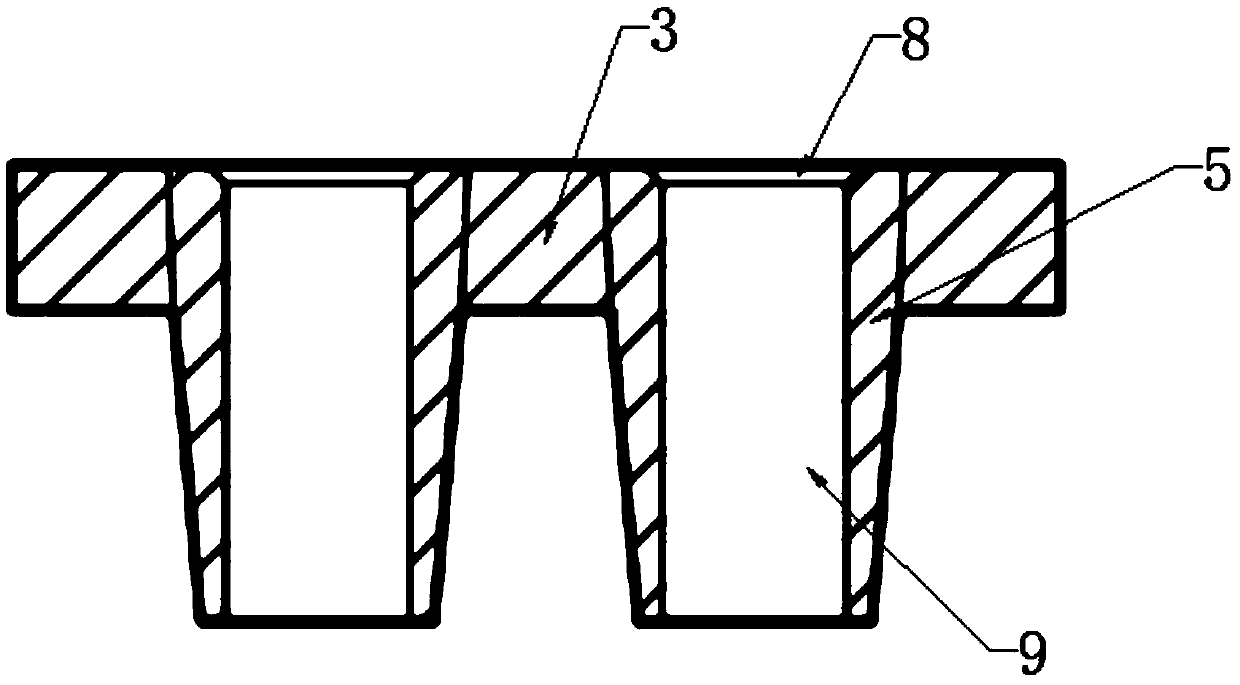
[0034] Such as Figure 1-5 As shown, a leaking plate of a 7.5um electronic yarn drawing equipment includes a plug 1, a bottom plate 3, an electrode 4, a leak nozzle 5 and a side wall 7, and a flow tank is formed between the side wall 7 and the bottom plate 3, and the bottom plate 3 is connected to There are several reinforcing ribs 2, the top of the side wall 7 is welded with a flange 6, the side wall 7 is provided with a thermocouple, and the thermocouple is located outside the flow tank, the electrode 4 is located on the plug 1, and the electrode 4 is located outside the flow tank , the electrode 4 is connected to the thermocouple on the side wall 7 through a couple tube, a number of leakage nozzles 5 are distributed on the bottom plate 3, and two rows of leakage nozzles 5 are arranged in a staggered manner, and a deflector 10 is arranged above the bottom plate 3.

[0035] The inside of the leak nozzle 5 is composed of an upper opening 8 and a lower opening 9, the upper open...

Embodiment 2

[0042] Such as Figure 5-7 As shown, the two ends of the deflector 10 are welded with lifting rods 13, and a number of diversion holes 11 are distributed on the deflector 10. The positions and numbers of the diversion holes 11 correspond to the nozzles 5, and the diversion holes 11 are in the shape of a funnel. shape, and the cross-section formed between two adjacent diversion holes 11 is an inverted V shape, the diversion holes 11 are adapted to the upper opening 8 of the leak nozzle 5, and the diversion holes 11 are set on the upper opening of the leak nozzle 5 within 8.

[0043] The deflector 10 is made of platinum-rhodium alloy, which generally contains 90% Pt and 10% Rh at present, and is strengthened by zirconium dispersion.

[0044] Since the leakage surface of the bottom plate 3 is flat, and the glass liquid has a certain viscosity, it is easy to cause the glass liquid to remain on the bottom plate 3, and the glass liquid will adhere to the leaking nozzle 5 of the lea...

Embodiment 3

[0046] Such as Figure 5-8 As shown, heat sinks 12 are welded between adjacent two rows of leak nozzles 5, and heat sinks 12 are nickel plates 14, and nickel plates 14 are provided with a plurality of through holes in parallel, and the inner diameter of the through holes is equal to the outer diameter of the copper pipe 15, and the copper pipe 15 penetrates into the inside of the nickel plate 14 along the through hole, and one end of the copper pipe 15 is communicated with the water inlet tank 16, and the other end of the copper pipe 15 is communicated with the drain tank 18, and the water inlet tank 16 is connected with the water inlet pipe 17, and the drain tank 18 is connected with drainpipe 19.

[0047] Through the setting of the heat sink 12, since the nickel plate 14 has the performance of high temperature resistance, it can dissipate heat on the leakage plate and the leaked glass fiber, and at the same time penetrate into the nickel plate 14 through the copper tube 15, ...


PUM

PropertyMeasurementUnit
thicknessaaaaaaaaaa

Abstract

The invention discloses leakage plate of 7.5 micrometer electronic yarn drawing equipment, which comprises a plug, a bottom plate, an electrode, a leakage nozzle and a side wall, wherein a liquid flowing groove is formed between the side wall and the bottom plate; a plurality of reinforcing ribs are connected on the bottom plate; a flanging is welded on the top of the side wall; an electric heating couple is arranged on the side wall; and the electric heating couple is positioned at the outer side of the liquid flowing groove; the electrode is positioned on the plug; a plurality of leakage nozzles are distributed on the bottom plate; two rows of leakage nozzles are arranged in parallel in a staggered manner; and a guide plate is arranged above the bottom plate. According to the invention,compared with the existing six-division pull E225-1200H leakage plate, the leakage plate of the 7.5 micrometer electronic yarn drawing equipment, has the improved eight-division pull E225-1600H leakage plate, so that the glass liquid flow rate is improved, and the production efficiency is improved; the adjustment of the thickness of the electrode improves the temperature of the settable leakage plate; the aperture of the leakage plate increases by 0.1mm compared with that of the six-division pull E225 leakage plate, and the flow rate of the glass liquid increases at the same temperature of theleakage plate, so that the aim of improving the wire drawing rotating speed is achieved; and the distribution of the peripheral leakage nozzles is optimized, and the quality abnormality such as fly filament, hairiness and the like easily caused by larger tension compared with other areas is reduced.

Description

technical field [0001] The invention relates to the field of glass fiber primary twisted yarn, in particular to a bushing plate of a 7.5um electronic yarn drawing equipment. Background technique [0002] The existing E225 drain plate is mainly 1200H, that is, six partitions, and there are fewer partitions, resulting in low glass liquid flow per unit time and low efficiency. The thickness of the six-point drawing electrode and the aperture of the leak nozzle should not be set at a high temperature, which cannot meet the requirements of the high-speed wire drawing process. During the use of the six-point leaking plate, the temperature of the leak nozzle in the periphery of the single zone is lower than that of other zones, and the tension is too high compared with other zones, which may cause abnormal quality such as flying silk and hairiness. [0003] Main problems and disadvantages: [0004] 1. Liufenla E225-1200H has fewer partitions, low production efficiency, high unit ...

Claims


Application Information

Patent Timeline
Patent Type & Authority Applications(China)
IPC IPC(8): C03B37/08
CPCC03B37/08
Inventor 张斌李伟于万春
Owner LINZHOU GUANGYUAN NEW MATERIAL TECH
Why Eureka
Try Eureka