Visual fuel rod

A fuel rod and fuel cladding technology, applied in the field of nuclear reactors, can solve the problems of velocity vector image distortion, measurement velocity error, difficulty in obtaining velocity vector diagram, etc., and achieve the effect of meeting the requirements of mechanical strength and facilitating collimation and installation

Active Publication Date: 2019-04-19
INST OF MODERN PHYSICS CHINESE ACADEMY OF SCI
View PDF6 Cites 3 Cited by
  • Summary
  • Abstract
  • Description
  • Claims
  • Application Information

AI Technical Summary

Problems solved by technology

[0004] If the selected fuel rods and working medium have poor light transmittance, it will be difficult or even impossible for the laser sheet light source to penetrate the fuel rods, which will make it difficult to obtain a clear velocity vector diagram during the experiment
If the refr

Method used


Image

  • Visual fuel rod
  • Visual fuel rod
  • Visual fuel rod

Examples


Embodiment Construction

[0023] In order to make the object, technical solution and advantages of the present invention clearer, the present invention will be described in further detail below in conjunction with specific embodiments and with reference to the accompanying drawings.

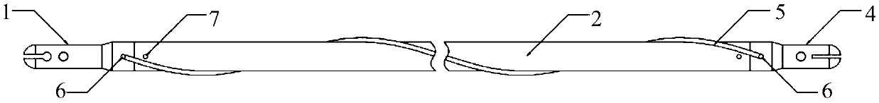
[0024] One of the tasks of nuclear reactor thermal analysis is to analyze the temperature distribution of fuel elements and the flow and heat transfer characteristics of coolant. Liquid metal cooling fast reactor fuel rods and coolant are all made of metal, and typical non-contact optical velocimetry (such as particle image velocimetry) cannot obtain flow field data inside the component, so the present invention provides a visual fuel rod In order to meet the requirements of the optical velocity measuring device on the refractive index matching and light transmission of the fuel rod and the working medium.

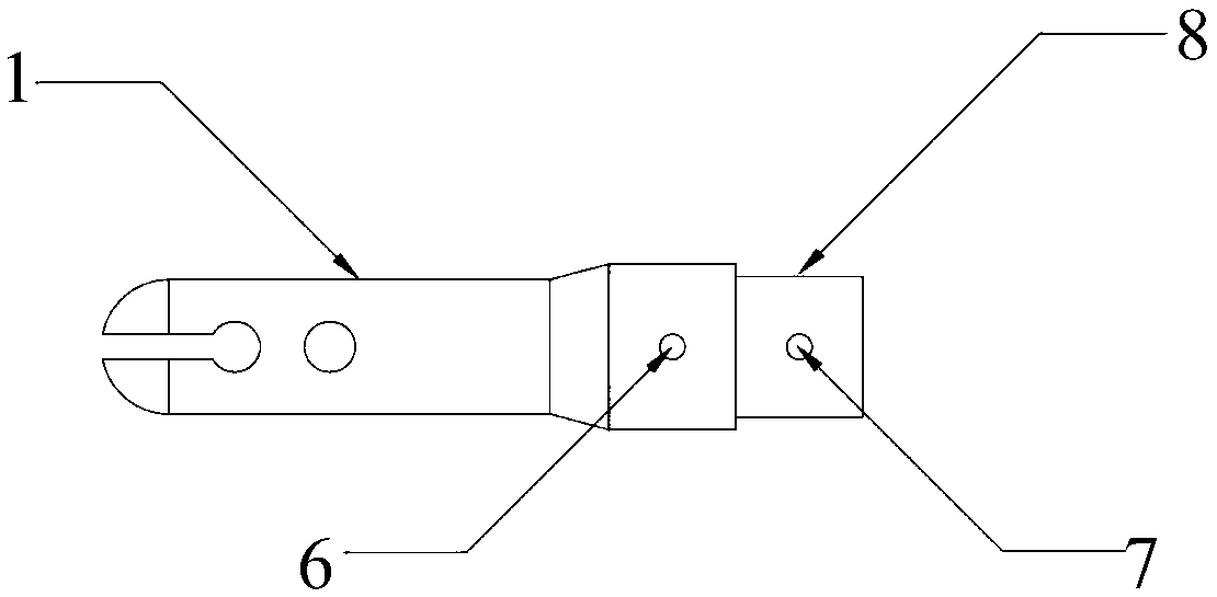
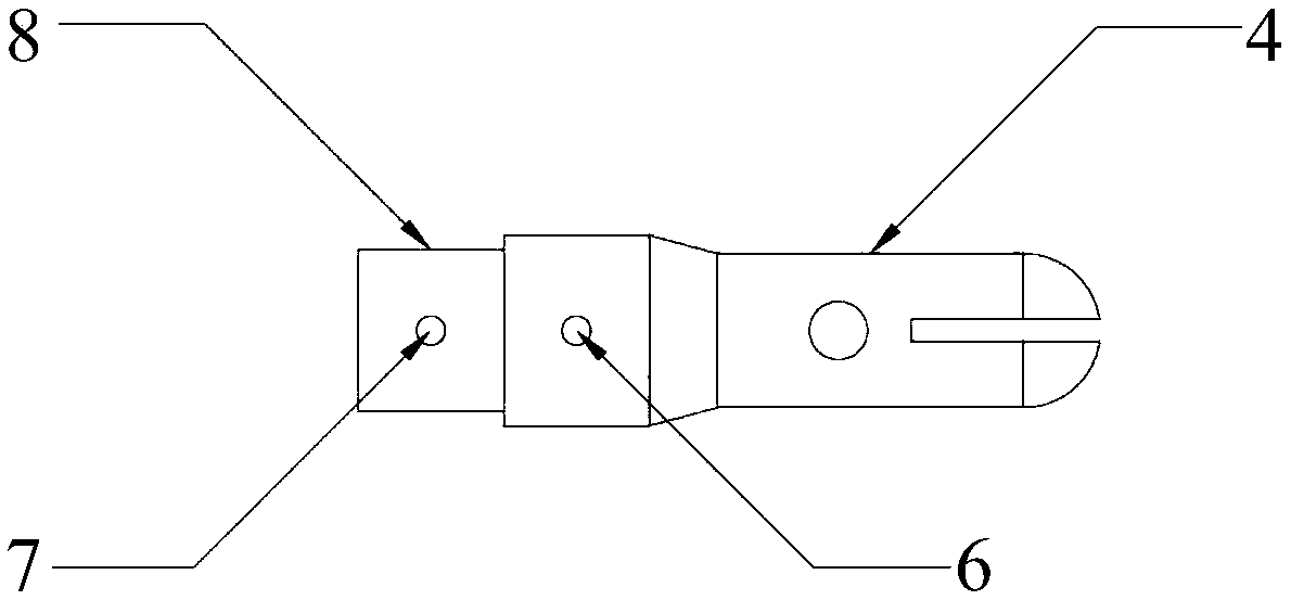
[0025] The present invention provides a visual fuel rod, comprising: a lower end plug 1, a fuel cladding 2, a liqui...


PUM


Abstract

The invention provides a visual fuel rod. The visual fuel rod is characterized in that the visual fuel rod includes a lower plug (1), a fuel shell (2), a liquid column (3), an upper plug (4) and a positioning winding wire (5). The liquid column (3) is arranged in the fuel shell (2). The refractive index deviation of the liquid column (3) and the fuel shell (2) is within a range of 1%. The lower plug (1) and the upper plug (4) are connected to the two ends of the fuel shell (2) so as to seal the liquid column (3) in the fuel shell (2). The positioning winding wire (5) wraps and is fixed to theouter surface of the fuel shell (2). Through the arrangement of liquid with the same or similar refractive index with the fuel shell (2) in the fuel shell (2), the requirements of optical velocity measuring equipment for refractive index matching and transmittance can be satisfied, and the requirements of mechanical strength can be satisfied. The visual fuel rod can be used for studying a velocityfield, a pressure field and the like inside a fuel assembly.

Description

technical field [0001] The invention relates to the field of nuclear reactors, in particular to a visual fuel rod. Background technique [0002] Fuel assembly is a heat source with compact structure and high heat release rate per unit volume, and it is exposed to strong radiation for a long time. A typical liquid metal-cooled fast reactor fuel rod is a fuel rod bundle whose radial positioning is maintained by a spiral positioning wire or a grid-shaped positioning frame, and the axial positioning is maintained by a grid plate. The fuel rods are arranged in an equilateral triangle grid. The fuel assembly with positioning wires has a complex structure, dense flow channels, and lateral mixing, which can enhance heat transfer and reduce the probability of blockage. [0003] Liquid metal coolant is opaque, and non-contact optical velocity measurement technology cannot be used to observe the flow field inside the component. At the same time, liquid metal-cooled fast reactors oper...

Claims


Application Information

Patent Timeline
IPC IPC(8): G21C3/24G21C3/07
CPCG21C3/07G21C3/24Y02E30/30
Inventor 范大军顾龙彭天骥唐延泽田旺盛范旭凯王冠刘璐李金阳王大伟张璐于锐秦长平姜韦崔青蓝
Owner INST OF MODERN PHYSICS CHINESE ACADEMY OF SCI
Why Eureka
Try Eureka