High-energy electron detecting device for long-gap pulse discharge process

A technology of pulse discharge and high-energy electrons, applied in the direction of testing dielectric strength and using optical methods to test, etc., can solve problems affecting the measurement waveform, limited energy of the device, traveling wave refraction, etc., to improve authenticity and accuracy, eliminate Effect of Impedance Mismatch and Lower Emission Coefficient

Active Publication Date: 2019-04-23
CHINA ELECTRIC POWER RES INST +3
View PDF10 Cites 0 Cited by
  • Summary
  • Abstract
  • Description
  • Claims
  • Application Information

AI Technical Summary

Problems solved by technology

[0003] Chinese invention patent, publication number CN 106646578 A, discloses a high-energy proton beam current density distribution test device. The Faraday cup and mobile platform are placed in a vacuum as a whole. Although it is less affected by external interference, the device is complex and bulky. Larger, difficult to measure high-energy electron beam currents in long-gap discharges
Chinese invention patent, publication number CN101615578 A discloses a method for detecting plasma The Faraday cup without dose injection, the Faraday cup is an inverted horn-type hollow structure, which eliminates the influence of secondary electron emission generated by high-energy beams, but due to the structural limitations of this device, the inverted horn opening design cannot be used in the discharge process. High Energy Electron Beam Acquisition
Chinese invention patent, publication number CN102280345 A discloses a Faraday cup with one end open and one end sealed. A metal shield structure is added outside the ion collection cup, which can shield the interference caused by the scattered ions inside the vacuum cavity, so it can be accurately Effectively collect the target, but does not consider the wave impedance matching problem of the Faraday cup. The voltage signal generated by the ion will produce large refraction due to the mismatch between the opening, seal and the main body impedance of the Faraday cup, causing waveform distortion.
Chinese invention patent, Publication No. CN103760590 A discloses a device for measuring escaped electron beams under nanosecond pulsed gas discharge, but the device is small in size and is suitable for measuring high-energy escaped electron beams in small discharge chambers. Collectively designed for entities, high-energy electrons bombard the collector at the end face of the collector to produce large secondary electron emissions that affect the measurement waveform. In addition, when designing the signal lead-out line and insulating sleeve, the impedance matching of the small area is not considered. The catadioptric reflection of traveling waves will occur when the signal is drawn out of the line
J.D.Thomas et.al. designed a limited-mouth Faraday cup to collect proton flow. The Faraday cup adopts a cylindrical structure and a built-in slope inside the Faraday cup. This slope is used to eliminate the secondary generated by protons on the collector. However, this device is limited to the collection of charged particle beams with lower energy, and is basically not suitable for the detection of particle beams with energies of hundreds of kiloelectronvolts or even megaelectronvolts.
[0004] The above technical solution does not solve the problem of how to realize the collection and measurement of high-energy electrons under meter-level long-gap discharge, different pressures, different gases, and different discharge distances when collecting and detecting high-energy electron beams in long-gap discharge experiments. Moreover, the collector in the above-mentioned technical solution is relatively bulky and cannot solve the influence of secondary electrons generated by high-energy electrons on the surface of the collector. At the same time, the above-mentioned technical solution does not solve the problem of the influence of waveform oscillation caused by impedance mismatch when the signal is drawn out , and the bandwidth and measurement accuracy of the above-mentioned technical solutions are low, and it is impossible to accurately and comprehensively measure the high-energy electron beam current in the long-gap discharge

Method used


Image

  • High-energy electron detecting device for long-gap pulse discharge process

Examples


Embodiment Construction

[0019] Exemplary embodiments of the present disclosure will be described in more detail below with reference to the accompanying drawings. Although exemplary embodiments of the present disclosure are shown in the drawings, it should be understood that the present disclosure may be embodied in various forms and should not be limited by the embodiments set forth herein. Rather, these embodiments are provided for more thorough understanding of the present disclosure and to fully convey the scope of the present disclosure to those skilled in the art. It should be noted that, in the case of no conflict, the embodiments of the present invention and the features in the embodiments can be combined with each other. The present invention will be described in detail below with reference to the accompanying drawings and examples.

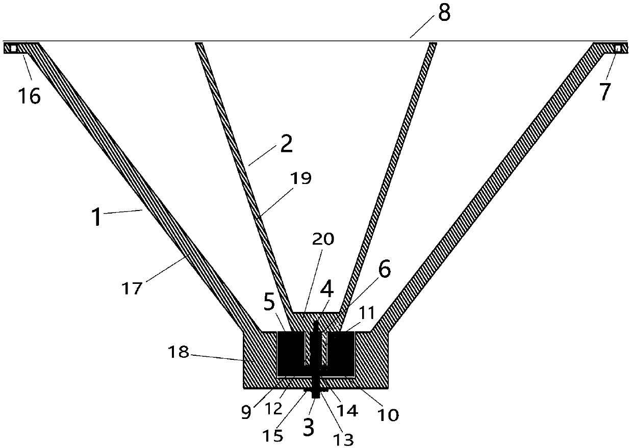
[0020] refer to figure 1 As shown, this embodiment provides a high-energy electronic detection device in the long-gap pulse discharge process, including: a h...


PUM


Abstract

The invention provides a high-energy electron detecting device for a long-gap pulse discharge process. The high-energy electron detecting device comprises a shell, a charge collecting body, an sub-miniature-A (SMA) interface, a connector, a first insulating isolation part and a metal plate, wherein the shell and the charge collecting body are both of a hollow structure with one end open, the charge collecting body is inserted into the shell, the shell and the charge collecting body are identical in open direction, and central axes of the shell and the charge collecting body coincide, wherein afirst groove is formed in the middle of the inner bottom face of the shell, and the first insulating isolation part is arranged in the first groove in a sleeved mode; a third groove is formed in thelower side face of a protruding part, the connector is inserted into the third groove, the upper end of the connector is connected with the charge collecting body, and the lower end of the connector is connected with the input end of the SMA interface; the metal plate covers the open end of the shell to enable a closed cavity to be formed in the shell. The collecting end of the charge collecting body is of an open hollow structure, and thus the weight of a measuring device is effectively lowered, the secondary electron yield can be effectively lowered, and the reality of the waveform is guaranteed.

Description

technical field [0001] The invention relates to the technical field of long-gap discharge, in particular to a high-energy electronic detection device during long-gap pulse discharge. Background technique [0002] At present, a very high local field strength will be generated in the long gap discharge process, and the initial electrons in the space or the electrons generated by the field emission will obtain extremely high energy under the acceleration of the electric field. The resistance received is much smaller than the electric field force, and the electrons will be accelerated all the time. These high-energy electrons cause the pre-ionization of the air gap, which has an important impact on the development, shape, and speed of the discharge. The detection of these high-energy electrons is important for studying the long-gap discharge mechanism. meaning. [0003] Chinese invention patent, publication number CN 106646578 A, discloses a high-energy proton beam current dens...

Claims


Application Information

Patent Timeline
IPC IPC(8): G01R31/12
CPCG01R31/1218
Inventor 章程丁玉剑邵涛邱锦涛庄池杰贺恒鑫姚修远
Owner CHINA ELECTRIC POWER RES INST
Why Eureka
Try Eureka