Outer part and component of mask plate, color filter substrate and manufacturing method, display panel

A technology of color filter substrate and mask plate, which is applied in the fields of instruments, nonlinear optics, optics, etc., and can solve the problems of affecting production line production tempo, affecting product yield, increasing costs, etc.

Active Publication Date: 2021-11-16
BOE TECH GRP CO LTD +1
View PDF6 Cites 0 Cited by
  • Summary
  • Abstract
  • Description
  • Claims
  • Application Information

AI Technical Summary

Problems solved by technology

[0002] With the development of display technology, users demand that liquid crystal display products have higher color saturation and color gamut. In order to meet customer needs, the existing technology increases the color saturation by increasing the thickness of the color filter film and matches the corresponding backlight. To realize the high color gamut of the product, but the above-mentioned prior art has the following problems: such as figure 1 As shown, due to the increase in the thickness of the color filter film layer, a large step difference D1 is formed between the blue virtual pattern 101' around the color filter substrate and the substrate surface (wherein, the maximum value of D1 reaches 3.0 μm), resulting in subsequent transparent When the protective layer 102'(OC) is coated, the film breaks at the level difference
like figure 2 As shown, the light-colored stripes in area I are the location where the protective layer breaks, which seriously affects the product yield.
[0003] In order to solve the above problems, the existing technology solves the occurrence of film rupture by reducing the coating speed of the protective layer or increasing the film thickness of the protective layer. However, reducing the coating speed of the protective layer will affect the production cycle of the production line and reduce the production capacity. , increasing the thickness of the protective layer will reduce the transmittance and increase the cost

Method used


Image

  • Outer part and component of mask plate, color filter substrate and manufacturing method, display panel
  • Outer part and component of mask plate, color filter substrate and manufacturing method, display panel
  • Outer part and component of mask plate, color filter substrate and manufacturing method, display panel

Examples


Embodiment Construction

[0046] Specific embodiments of the present invention will be described in detail below in conjunction with the accompanying drawings. It should be understood that the specific embodiments described here are only used to illustrate and explain the present invention, and are not intended to limit the present invention.

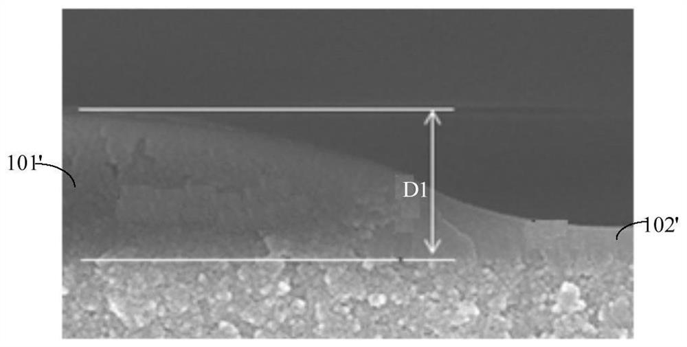
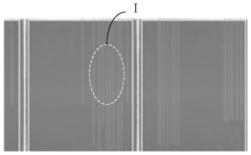
[0047] Since in the prior art, due to the increase in the thickness of the color filter film layer, a large step difference is formed between the virtual graphics around the color filter substrate and the surface of the substrate, the inventors of the present invention considered designing and forming the virtual graphics at the extension position of the virtual graphics after in-depth research. A buffer strip to reduce said step difference.

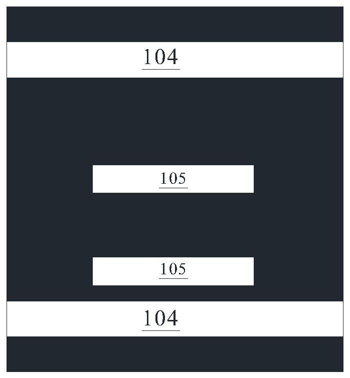
[0048]In view of this, as a first aspect of the present invention, there is provided an outer part of a mask plate, the outer part of a mask plate is used for making a color filter on a color filter substrate, and the colo...


PUM


Abstract

The present invention provides an outer part of a mask plate, the outer part of the mask plate is used for making a color filter of a color filter substrate, and the color filter substrate includes a pixel area and a dummy area located at least one side of the pixel area. The outer part of the mask plate includes a light-shielding layer and a light-transmitting pattern formed in the light-shielding layer, and the light-transmitting pattern includes a pixel light-transmitting pattern and a virtual light-transmitting pattern, wherein the virtual light-transmitting pattern includes A first virtual light transmission pattern on at least one side of the light pattern and at least one second virtual light transmission pattern located outside the first virtual light transmission pattern, the second virtual light transmission pattern includes a plurality of virtual pattern units, the The area of ​​the virtual graphic unit is inversely related to the distance on one side of the first virtual light-transmitting graphic corresponding to the virtual graphic unit. The invention also provides a mask plate assembly, a color filter substrate and a manufacturing method of the color filter substrate. The film breaking rate of the color filter substrate is relatively low.

Description

technical field [0001] The present invention relates to the field of liquid crystal display, in particular to a mask outer part, a mask assembly including the mask outer part, a color filter substrate manufactured by using the mask assembly and a manufacturing method thereof, and a mask assembly including the mask assembly. The display panel of the color filter substrate. Background technique [0002] With the development of display technology, users demand that liquid crystal display products have higher color saturation and color gamut. In order to meet customer needs, the existing technology increases the color saturation by increasing the thickness of the color filter film and matches the corresponding backlight. To realize the high color gamut of the product, but the above-mentioned prior art has the following problems: such as figure 1 As shown, due to the increase in the thickness of the color filter film layer, a large step difference D1 is formed between the blue v...

Claims


Application Information

Patent Timeline
Patent Type & Authority Patents(China)
IPC IPC(8): G02F1/1335
CPCG02F1/133512G02F1/133514G02F1/133516
Inventor 黎敏熊强万彬戴于力
Owner BOE TECH GRP CO LTD
Why Eureka
Try Eureka