A carrier rocket video image interpretation error correction method

A carrier rocket and error interpretation technology, which is applied in the direction of instruments, geometric CAD, calculation, etc., can solve problems affecting the effect of error correction and achieve the effect of reliable data basis

Active Publication Date: 2019-04-23
CHINA XIAN SATELLITE CONTROL CENT
View PDF3 Cites 4 Cited by
  • Summary
  • Abstract
  • Description
  • Claims
  • Application Information

AI Technical Summary

Problems solved by technology

[0004] The purpose of the present invention is to provide a method for correcting the interpretation error of the video image of the launch vehicle, which solves the problem that the traditional one-sided interpretation error correction method is restrictive and affects the effect of error correction

Method used


Image

  • A carrier rocket video image interpretation error correction method
  • A carrier rocket video image interpretation error correction method
  • A carrier rocket video image interpretation error correction method

Examples


specific Embodiment

[0078] Taking a test mission as an example, the specific implementation process of video image interpretation, correction, fusion, lateral drift calculation, and rocket attitude determination of multiple launch vehicles is given.

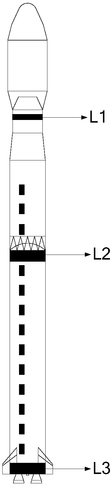
[0079] First of all, data preparation is carried out. In the video imaging data of the vertical take-off section of the launch vehicle tracked and measured by the high-speed TV measuring instrument, any measurement ring on the launch vehicle is selected, such as figure 1 Interpretation of the measurement loop L1, L2 or L3 in the rocket to obtain the time series measurement data from the rocket ignition take-off to the rocket out of the tower;

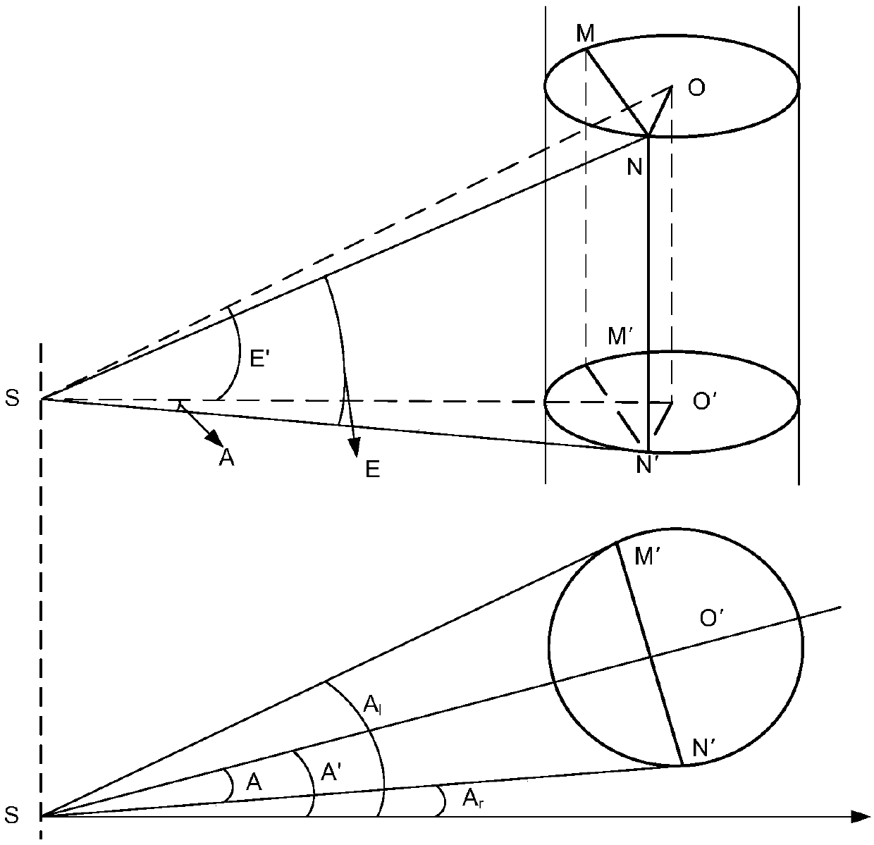
[0080] Then correct the interpretation error: figure 2 As shown, let the edge points on the left and right sides of the measurement ring be N and M respectively, S is the site center of the high-speed TV measuring instrument tracking equipment, and o is the center point of the measurement ring:

[0081] The...


PUM


Abstract

The invention discloses a carrier rocket video image interpretation error correction method. The method belongs to the technical field of spaceflight measurement and control, and comprises the following steps of firstly, tracking and measuring video imaging data of a vertical take-off section of a carrier rocket by a high-speed television measuring instrument, selecting any one characteristic point on the carrier rocket to obtain angle measurement data of two side edges of a measurement ring of the characteristic point in an observation station coordinate system, and performing error correction to obtain a corrected angle. According to the method disclosed by the invention, after the bilateral interpretation error is corrected, the transverse drift and the attitude of the carrier rocket can be accurately calculated, the flight state of the rocket is prevented from being mistakenly estimated, and an accurate and reliable data basis is provided for analyzing the rocket model and evaluating the flight performance of the rocket.

Description

technical field [0001] The invention belongs to the technical field of aerospace measurement and control, and relates to a correction method for video image interpretation errors of launch vehicles. Background technique [0002] In the aerospace test range, the high-speed TV measuring instrument is used to complete the tracking and measuring task of the vertical take-off section of the launch vehicle. After the image information of the rocket body recorded by it is effectively collected, interpreted, and error corrected, it is then passed through multiple tracking and measuring instruments. Data fusion calculation completes the lateral drift and attitude determination of the rocket. The calculation results are used in the flight performance analysis of the launch vehicle, which is of great significance for improving the structure of the rocket body, improving the performance of the test and launch system, and improving the safety of the launch process. Foreign countries att...

Claims


Application Information

Patent Timeline
Patent Type & Authority Applications(China)
IPC IPC(8): G06F17/50
CPCG06F30/15G06F30/20
Inventor 崔书华张伟胡绍林乜铁宁刘军王敏张冬波余慧郑雨西杨小燕陈钦苟茹君孙廓贾冰鲁自虎张力陈虓
Owner CHINA XIAN SATELLITE CONTROL CENT
Why Eureka
Try Eureka