A system for improving wheel-rail adhesion of trains

A technology of adhesion and train wheels, which is applied to locomotives and other directions, can solve the problems that it is difficult for sand to enter between the wheel and rail, increase the adhesion of wheel and rail, and the adhesion coefficient of wheel and rail is small, so as to achieve easy operation and stable adhesion of wheel and rail , long service life effect

Active Publication Date: 2020-08-18
TONGJI UNIV
View PDF9 Cites 0 Cited by
  • Summary
  • Abstract
  • Description
  • Claims
  • Application Information

AI Technical Summary

Problems solved by technology

However, due to the higher the running speed of the train and the smaller the adhesion coefficient of the wheel and rail, trains of different speed grades have different functional requirements for sand spreading. It is difficult for sand to enter between the wheel and rail at high speed, and the effect is not good. There is a common problem of sand spreading off track at small curve radii
In addition, the amount of sand installed in the sand spreading system on the train also limits the running distance of the train under certain circumstances, so there is an urgent need for a new technology to increase the wheel-rail adhesion

Method used


Image

  • A system for improving wheel-rail adhesion of trains
  • A system for improving wheel-rail adhesion of trains
  • A system for improving wheel-rail adhesion of trains

Examples


Embodiment 1

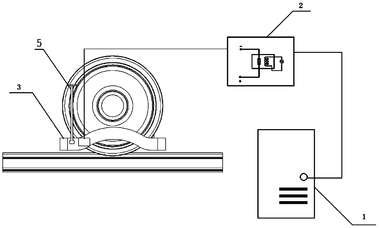
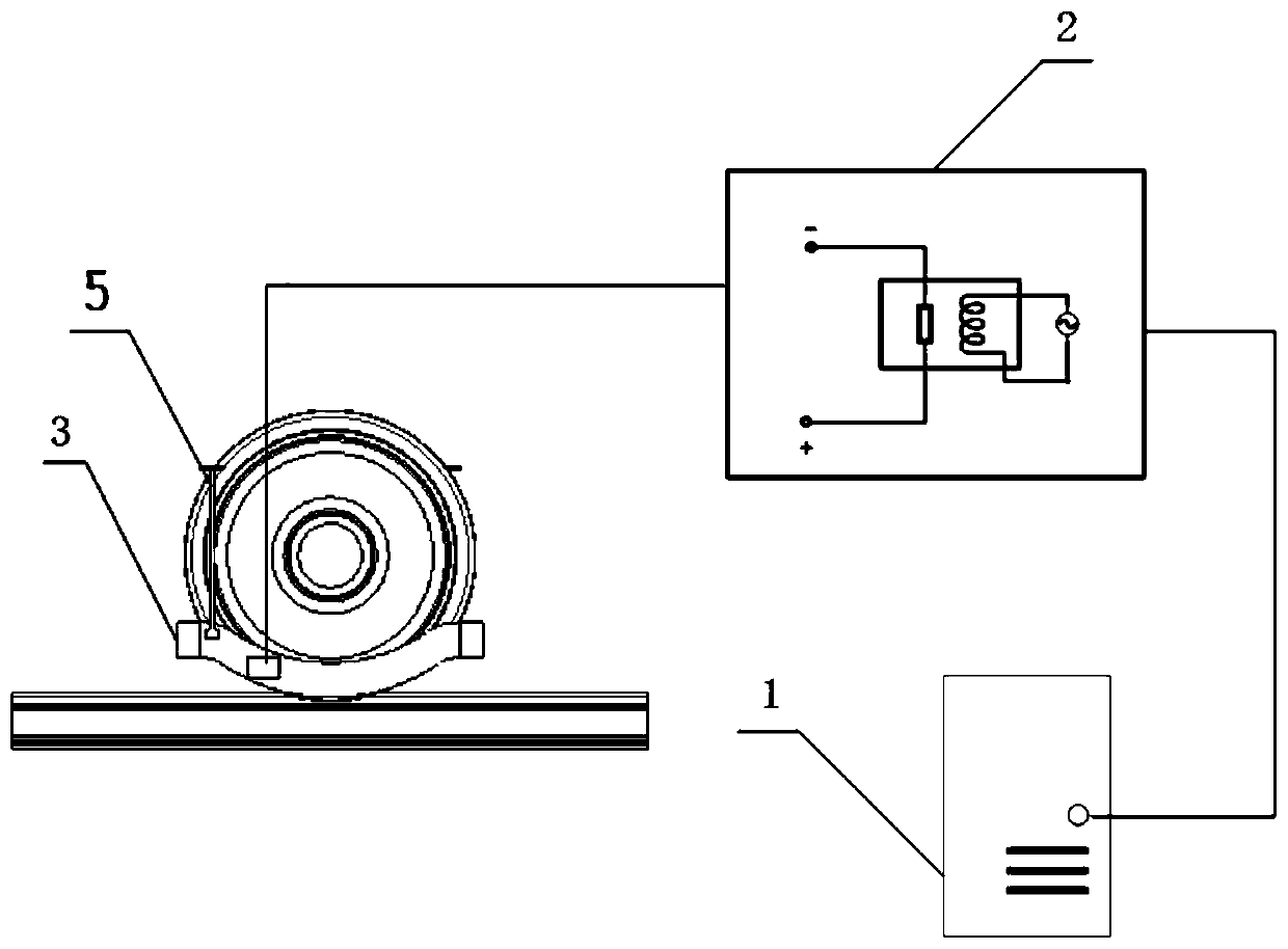
[0034] A system for improving the wheel-rail adhesion of a train, comprising a control assembly 1, a power supply 2, and an electromagnetic coil assembly 3 connected in sequence through lines, the electromagnetic coil assembly is wrapped around the train wheels, and the power supply 2 is used for Provide current to the electromagnetic coil assembly 3, at this time, the train wheel and the surrounding electromagnetic coil assembly form a large electromagnet, forming a magnetic field near the train wheel and the track, and the wheels surrounding the electromagnetic coil generate electromagnetic adsorption force on the rail, thereby increasing the strength of the vehicle. The vertical force acting on the rail, under the condition of the original wheel-rail adhesion coefficient, realizes the effect of improving the wheel-rail adhesion of the train. The control component is used to issue instructions to the power supply, and adjust the output current of the power supply through the i...

Embodiment 2

[0043] Different from Embodiment 1, this embodiment adopts another shape and structure of the coil housing 32 .

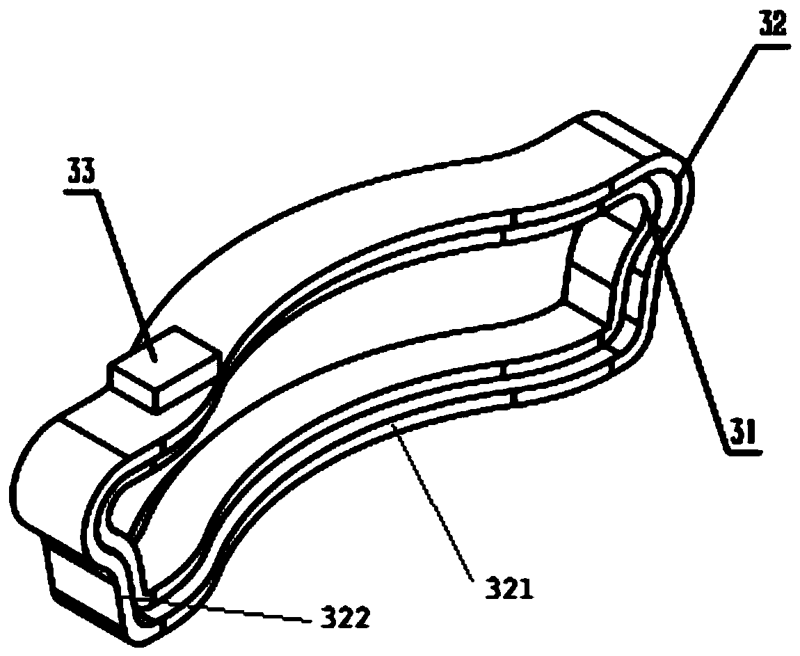
[0044] The electromagnetic coil assembly 3 includes an excitation coil 31 , a coil casing 32 and a junction box 33 , the excitation coil 31 is wound in the coil casing 32 , and the junction box 33 is arranged on the coil casing 32 . The excitation coil 31 and the coil casing 32 are annular structures, which include long sides 321 non-contactingly arranged on both sides of the rim of the train wheel and short sides 322 non-contactingly arranged on both sides of the wheel tread. The long side 321 described is a downward convex "saddle" shape structure, see image 3 , Figure 4 and Figure 5 . During the operation of this solution, the excitation coil 31 bends downward along the edge of the lower rim of the wheel, ensuring a uniform gap between the excitation coil 31 and the wheel rim, rim, and tread, thereby reducing magnetic flux leakage.

Embodiment 3

[0046] Different from Embodiment 1, the boom 5 is further improved into a telescopic boom, so as to realize the convenience of specific adjustment. For the specific structure, please refer to Figure 6 . The boom 5 is a telescopic boom, and the telescopic boom includes a sleeve 51, a rod 52 and a mounting seat 53, and the sleeve 51 is connected to the mounting seat 53 and is fixed to the rail of the train through the mounting seat 53. On the bogie frame, one end of the rod 52 is movably nested in the sleeve 51 to realize expansion and contraction, and the other end is connected to the coil casing 32 . The electromagnetic coil assembly (3) matched in this embodiment is a horizontal annular structure, wherein the excitation coil 31 also adopts a horizontal winding form. For the telescopic suspension rod in this embodiment, it can be installed according to The specific structure of the train and the standard of the track to make the adjustment of the corresponding upper and lowe...


PUM


Abstract

The invention relates to a system for improving wheel-track adhesive force of a train. The system comprises a control component (1), a power supply (2) and a solenoid coil component (3) connected in sequence by virtue of circuits, wherein the solenoid coil component (3) winds around the periphery of train wheels; the power supply (2) is used for providing current for the solenoid coil component (3); after the solenoid coil component (3) is conducted with current, a magnetic field is generated around the train wheels and the steel track, so that the train wheel generate adsorption force on thesteel tracks, and the wheel-track adhesive force of the train is improved; and the control component (1) is used for transmitting an instruction to the power supply (2), and the size and direction ofthe current output by the power supply (2) is regulated by the instruction. Compared with the prior art, the system disclosed by the invention has the advantages of being simple in system structure, convenient to mount, flexible to control, capable of obviously improving the wheel-track adhesive force, nondestructive to the steel tracks and wheels, and the like.

Description

technical field [0001] The invention relates to a train braking or traction system, in particular to a system for improving the wheel-rail adhesion of a train. Background technique [0002] Train traction and braking are mainly achieved by the adhesion between the wheels and rails. With the continuous development of high-speed and heavy-duty trains, the adhesion between the wheels and rails is required to be sufficiently large in the process of increasing traction or braking power. When the train is running at high speed, the adhesion coefficient between the wheel and rail will be greatly reduced. When the traction force or braking force of the train is greater than the maximum adhesion force between the wheel and rail, the train wheels will idling or slide, which cannot realize the normal operation of the train, and even endanger the driving safety. Therefore, it is urgent to study the technology that can increase the adhesion force between the wheel and rail. equipment. ...

Claims


Application Information

Patent Timeline
Patent Type & Authority Patents(China)
IPC IPC(8): B61C15/08
CPCB61C15/08
Inventor 应之丁樊嘉慧陈家敏梁晖
Owner TONGJI UNIV
Why Eureka
Try Eureka