Method for rapidly sintering NBT piezoelectric ceramic at low temperature

A piezoelectric ceramic and rapid sintering technology, which is applied in the field of low-temperature rapid sintering of NBT piezoelectric ceramics, can solve the problems of grain growth, the appearance of impurity phases, and the performance degradation of NBT piezoelectric ceramics, and achieves broad application prospects and simple methods.

Inactive Publication Date: 2019-04-26
SHAANXI UNIV OF SCI & TECH
View PDF5 Cites 4 Cited by
  • Summary
  • Abstract
  • Description
  • Claims
  • Application Information

AI Technical Summary

Problems solved by technology

However, during the sintering process, impurity phases or abnormal grain growth often appear, resulting in a decrease in the performance of NBT piezoelectric ceramics.

Method used


Image

  • Method for rapidly sintering NBT piezoelectric ceramic at low temperature
  • Method for rapidly sintering NBT piezoelectric ceramic at low temperature
  • Method for rapidly sintering NBT piezoelectric ceramic at low temperature

Examples


Embodiment 1

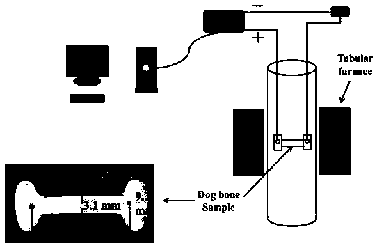
[0026] The NBT ceramic powder was pressed into a dog-bone-shaped green body by molding technology, and then pressed under 200MPa cold isostatic pressing for 180s. Place the NBT ceramic green body in the sintering furnace, and connect the green body to the DC high voltage power supply through platinum wires, such as figure 1 shown. Set the electric field to 120V / cm, and the limiting current density to 30mA / mm 2 , then raise the temperature of the sintering furnace from room temperature to 850°C, the heating rate is 10°C / min, the power supply is changed from constant voltage mode to constant current mode, and after keeping for 30s, turn off the power supply, and the furnace cools down to room temperature at 1~10°C / min, take out sample.

Embodiment 2

[0028] The NBT ceramic powder was pressed into a dog-bone-shaped green body by molding technology, and then pressed under 200MPa cold isostatic pressing for 180s. Place the NBT ceramic green body in the sintering furnace, and connect the green body to the DC high voltage power supply through platinum wires, such as figure 1 shown. Set the electric field to 140V / cm, and the limiting current density to 30mA / mm 2 , then raise the temperature of the sintering furnace from room temperature to 910°C, the heating rate is 10°C / min, the power supply is changed from constant voltage mode to constant current mode, after keeping for 30s, turn off the power supply, and the furnace cools down to room temperature at 1~10°C / min, take out sample.

Embodiment 3

[0030] The NBT ceramic powder was pressed into a dog-bone-shaped green body by molding technology, and then pressed under 200MPa cold isostatic pressing for 180s. Place the NBT ceramic green body in the sintering furnace, and connect the green body to the DC high voltage power supply through platinum wires, such as figure 1 shown. Set the electric field to 160V / cm, and the limiting current density to 30mA / mm 2 , then raise the temperature of the sintering furnace from room temperature to 960, the heating rate is 10°C / min, the power supply is changed from constant voltage mode to constant current mode, after keeping for 30s, turn off the power supply, and the furnace cools down to room temperature at 1~10°C / min, take out sample.

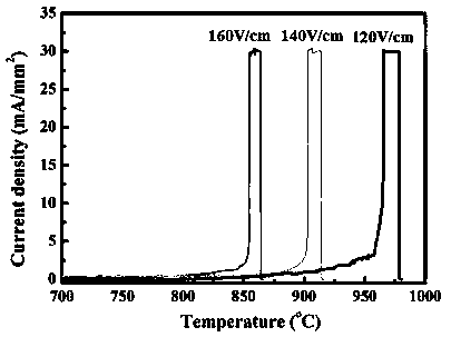
[0031] figure 2 It is the change curve of current density with furnace temperature for different electric fields (120V / cm, 140V / cm, 160V / cm). It can be seen from the figure that the corresponding rapid sintering temperature of ceramics decreases s...


PUM

PropertyMeasurementUnit
strengthaaaaaaaaaa

Abstract

The invention discloses a method for rapidly sintering an NBT piezoelectric ceramic at a low temperature. According to the method, an electric field is applied to both ends of a ceramic blank when theNBT piezoelectric ceramic is sintered. Under the action of the electric field, rapid densification of the ceramic can be realized at the low temperature, and the problems of Bi element volatilizationand high energy consumption caused by long-time sintering of NBT at a high temperature in the traditional sintering process are solved. The NBT piezoelectric ceramic prepared with the method providedby the invention is high in density and has application prospects.

Description

technical field [0001] The field of the invention belongs to the technical field of preparation technology of electronic functional ceramics, and in particular relates to a method for rapidly sintering NBT piezoelectric ceramics at low temperature. Background technique [0002] Sodium bismuth titanate (Na 0.5 Bi 0.5 TiO 3 NBT for short) is an important class of A-site composite lead-free perovskite piezoelectric ceramics, which have the advantages of strong piezoelectric performance, easy doping, and good stability. Due to its excellent piezoelectric, ferroelectric, dielectric and other electrical properties, it can be widely used in high-tech fields such as electronics and aerospace to prepare electronic components such as sensors, transducers, ferroelectric memories, and dielectric capacitors. An electronic functional ceramic material with broad development prospects. [0003] Normally, the sintering temperature of NBT piezoelectric ceramics is above 1100°C, and the si...

Claims


Application Information

Patent Timeline
Patent Type & Authority Applications(China)
IPC IPC(8): C04B35/475C04B35/64
CPCC04B35/475C04B35/64C04B2235/3201
Inventor 蒲永平史瑞科郭旭李经纬杨梦蝶王雯师裕
Owner SHAANXI UNIV OF SCI & TECH
Why Eureka
Try Eureka