Method for generating quantum bit control signals

A technology for control signals and qubits, applied in the field of qubit control signal generation, can solve the problems of not meeting the test requirements of qubits, complexity, slow switching speed, etc., and achieve the effect of reducing capacity storage requirements

Active Publication Date: 2019-04-26
ORIGIN QUANTUM COMPUTING TECH (HEFEI) CO LTD
View PDF9 Cites 7 Cited by
  • Summary
  • Abstract
  • Description
  • Claims
  • Application Information

AI Technical Summary

Problems solved by technology

[0005] Another method for generating qubit control signals in the prior art is to use direct digital synthesizer (Direct Digital Synthesizer, DDS) technology to generate simple waveforms (such as continuous sine waves), but in most cases the qubit control signals are complex Arbitrary waveform signals, the signal generated by DDS technology cannot easily realize complex arbitrary waveform information due to the slow switching speed, so it does not meet the test requirements of qubits

Method used


Image

  • Method for generating quantum bit control signals
  • Method for generating quantum bit control signals
  • Method for generating quantum bit control signals

Examples


Embodiment 1

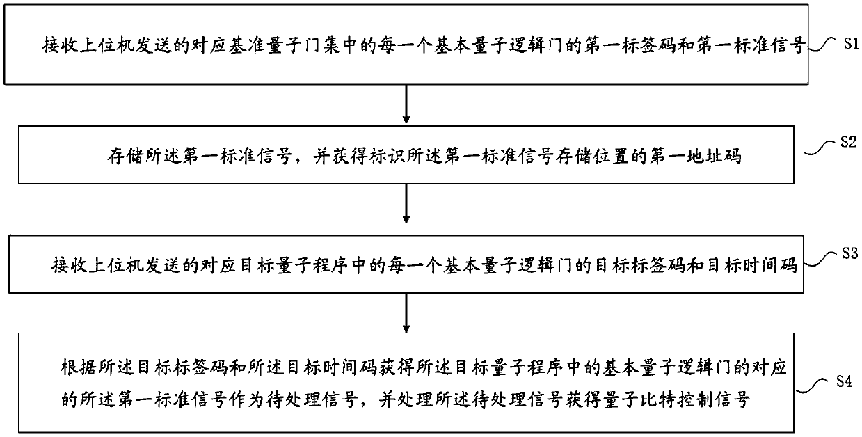
[0053] figure 1 It is a schematic flow chart of the qubit control signal generation method of the present application, such as figure 1 As shown, this embodiment provides a method for generating a qubit control signal, which is used to convert a quantum operation application into a basic qubit control signal, and finally send it to a quantum chip to perform the operation. It should be noted that the basic qubit control signal described here is not a control signal for completing the entire quantum chip operation application, but a basic signal for completing an operation step (ie, a target quantum program).

[0054] The qubit control signal generation method includes:

[0055] Step S1: Receive the first label code and the first standard signal of each basic quantum logic gate corresponding to the reference quantum gate set sent by the host computer; wherein: the reference quantum gate set refers to the basic quantum gates that can realize any quantum program through combinati...

Embodiment 2

[0089] Focusing on the convolution correction processing of the signal to be processed, this application provides a specific implementation scheme of a method for generating a qubit control signal based on Embodiment 1. The difference between this embodiment and Embodiment 1 is that it clarifies the The preparatory work and the specific process of the convolution correction processing of the signal to be processed are described.

[0090] Specifically, after storing the first standard signal and obtaining the first address code corresponding to the first label code, the qubit control signal generation method further includes: creating a A corresponding convolution code; wherein: the convolution code is in one-to-one correspondence with a preset convolution module, and the preset convolution module is used to perform convolution correction processing on the first standard signal.

[0091] That is, the convolver code and the convolver module are created inside the control module,...


PUM


Abstract

The invention belongs to the technical field of quantum chip testing, and particularly discloses a method for generating quantum bit control signals. The method includes the steps that a first tag code and a first standard signal of each basic quantum logic gate in a corresponding reference quantum gate set sent by an upper computer are received; the first standard signals are stored, and first address codes for identifying the storage positions of the first standard signals are obtained; a target tag code and a target time code of each basic quantum logic gate in a corresponding target quantum program sent by the upper computer are received; first standard signals corresponding to the basic quantum logic gates in the target quantum program are obtained according to the target tag codes and the target time codes to serve as to-be-processed signals, the to-be-processed signals are processed, and the quantum bit control signals are obtained. The multi-bit quantum bit testing requirementscan be met, and the quantum bit control signal requirements needed by multi-bit quantum bit testing are provided.

Description

technical field [0001] The invention belongs to the technical field of quantum chip testing, in particular to a method for generating a qubit control signal. Background technique [0002] Quantum chips are the core structure of quantum computers, and qubits are the basic computing units of quantum chips. When the quantum chip is running, it is necessary to provide reliable control signals to the qubits on the quantum chip to realize quantum testing. The qubit control signal acts on the qubits of the quantum chip, which can cause the quantum state of the target qubit to undergo a controllable and specified change, so as to realize the operation of the quantum logic gate. In the actual operation process, it is necessary to implement a series of quantum logic gate operations on the qubit, so the number and length of the qubit control signals will be greatly increased due to the type and number of quantum logic gate operations. [0003] One method of generating qubit control s...

Claims


Application Information

Patent Timeline
Patent Type & Authority Applications(China)
IPC IPC(8): G01R31/3183G01R31/28
CPCG01R31/282G01R31/318371
Inventor 孔伟成
Owner ORIGIN QUANTUM COMPUTING TECH (HEFEI) CO LTD
Why Eureka
Try Eureka