Ultra-low profile dual-band wide beam microstrip antenna based on multimode fusion

A microstrip antenna and profile technology, which is applied in the directions of antennas, antennas, and antenna components suitable for movable objects, can solve the problems of hindering the application of the antenna, increasing the height of the antenna profile, and being difficult to process, and achieves a high level of improvement. Effects of frequency impedance matching characteristics, reduced profile size, and low profile characteristics

Active Publication Date: 2019-04-26
西安天烁电磁技术有限公司
View PDF4 Cites 10 Cited by
  • Summary
  • Abstract
  • Description
  • Claims
  • Application Information

AI Technical Summary

Problems solved by technology

The cost is high, many materials are used, and the processing is difficult. The existing technology can achieve a certain degree of wide beam characteristics, but at the same time the profile height of the antenna will increase, such as technology 1 and technology 3; the processing difficulty will increase, such as technology 2. Technology 3: The above two points determine the increase in the cost of the antenna. In the case of maintaining a low profile and low processing complexity, realizing the wide beam characteristic of the antenna can make the application range of the wide beam antenna wider
[0003] Although the above antennas achieve the wide beam characteristics of microstrip antennas, the manufacturing costs of the antennas are relatively high, which hinders the application of antennas in ultra-low profile communication systems

Method used


Image

  • Ultra-low profile dual-band wide beam microstrip antenna based on multimode fusion
  • Ultra-low profile dual-band wide beam microstrip antenna based on multimode fusion
  • Ultra-low profile dual-band wide beam microstrip antenna based on multimode fusion

Examples


Embodiment Construction

[0030] In order to make the object, technical solution and advantages of the present invention more clear, the present invention will be further described in detail below in conjunction with the examples. It should be understood that the specific embodiments described here are only used to explain the present invention, not to limit the present invention.

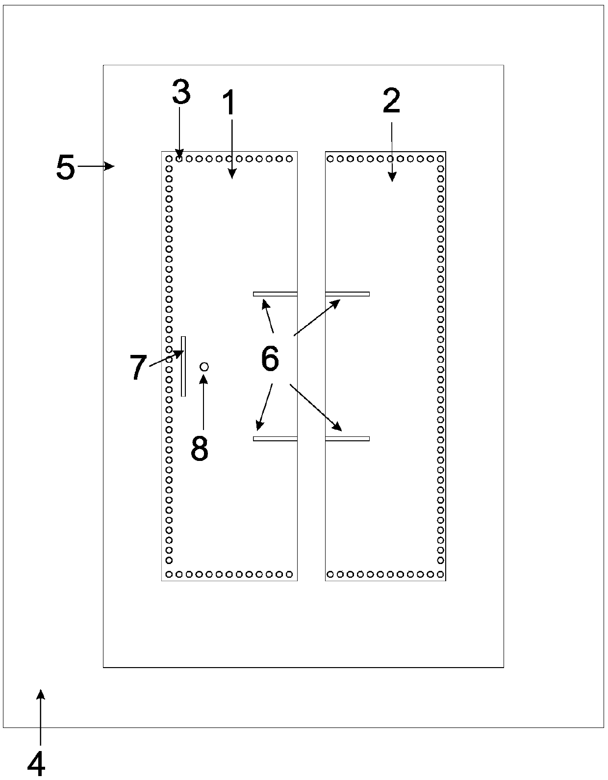
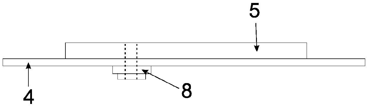
[0031] Aiming at the problem that the manufacturing cost of the existing antenna is relatively high, which hinders the application of the antenna in the ultra-low profile communication system. The invention can minimize the influence of the antenna on the shape of the carrier while ensuring the high performance of the antenna. In addition, the antenna technology of the present invention can also be used as a ship-borne and airborne phased array unit, which helps to obtain a high-performance wide-angle scanning phased array antenna.

[0032] The application principle of the present invention will be described in detail belo...


PUM


Abstract

The invention belongs to the technical field of wireless communication, and discloses an ultra-low profile dual-band wide beam microstrip antenna based on multimode fusion. A rectangular radiation microstrip and a rectangular parasitic microstrip are attached to a dielectric substrate, and are located at an uppermost layer of the antenna; the dielectric substrate is located on an intermediate layer of the ultra-low profile dual-band wide beam microstrip antenna based on the multimode fusion; a metal bottom plate is located on the lower layer of the dielectric substrate; a gap between the rectangular radiation microstrip and the rectangular parasitic microstrip is used for radiating rays to polarize electromagnetic waves; metal through holes are formed in the dielectric substrate along theedge of the rectangular radiation microstrip and the rectangular parasitic microstrip; the metal bottom plate is located at the lowermost portion of the entire antenna, and a radio frequency connectoris installed. The antenna meets the requirement of achieving a wide beam of the antenna under the low profile condition of a traditional microstrip antenna; while ensuring the high performance of theantenna, the influence of the antenna on the shape of a carrier can be minimized; an angular scan phase control array antenna with high performance is conveniently obtained.

Description

technical field [0001] The invention belongs to the technical field of wireless communication, and in particular relates to an ultra-low profile dual-band width beam microstrip antenna based on multi-mode fusion. Background technique [0002] At present, the existing technologies commonly used in the industry are as follows: low-profile antennas are more and more used in modern wireless communication technologies due to their low profile, small wind resistance, and easy conformity with carriers. Like microstrip antennas and planar helical antennas, for example, if the antenna is installed on the surface of the aircraft, the low-profile antenna can conform to the surface of the aircraft very well, and the antenna will not have additional aerodynamic effects on the aircraft itself. Because of its many advantages, microstrip antennas have been widely used in military and civilian fields since 1980. The beam width of the microstrip antenna can generally reach 70°-100°, which al...

Claims


Application Information

Patent Timeline
Patent Type & Authority Applications(China)
IPC IPC(8): H01Q1/38H01Q1/50H01Q5/10H01Q5/20H01Q5/307H01Q1/27H01Q1/28
CPCH01Q1/27H01Q1/285H01Q1/38H01Q1/50H01Q5/10H01Q5/20H01Q5/307
Inventor 刘能武李政佑傅光祝雷陈曦
Owner 西安天烁电磁技术有限公司
Why Eureka
Try Eureka