Active power factor correction DC power supply circuit and circuit method thereof
A technology of DC power supply and source power, applied in the direction of converting AC power input to DC power output, high-efficiency power electronic conversion, output power conversion device, etc., can solve problems such as limiting the performance of power factor correction circuits, and avoid adverse effects , Prevent oscillation phenomenon, shorten the effect of adjustment time
- Summary
- Abstract
- Description
- Claims
- Application Information
AI Technical Summary
Problems solved by technology
Method used
Image
Examples
Embodiment 1
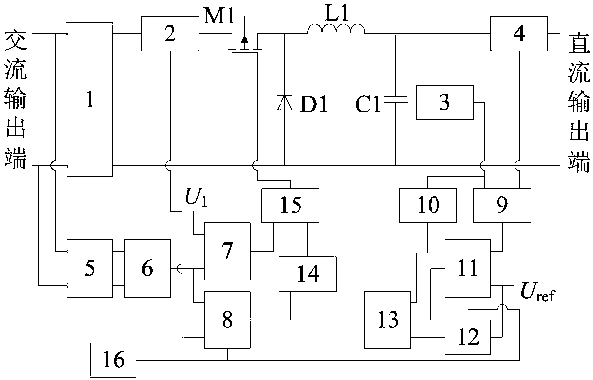
[0031] The active power factor correction DC power supply proposed by the present invention is composed of two major parts, a main circuit and a control circuit.
[0032] The main circuit is composed of the first and first rectification circuit 1, power electronic device M1, freewheeling diode D1, inductor L1 and capacitor C1. Among them, the power electronic device M1, the freewheeling diode D1, the inductor L1, and the capacitor C1 constitute a BUCK circuit; the control circuit is connected to the main circuit; the input end of the BUCK circuit is connected to the DC side of the first rectifier circuit 1, and the output of the BUCK circuit The terminal is connected to the external load of the power supply; the AC side of the first rectifier circuit 1 is connected to an external single-phase AC power supply.
[0033]The control circuit consists of an input current detection circuit 2, an output voltage detection circuit 3, an output current detection circuit 4, an AC voltage ...
Embodiment 2
[0055] The active power factor correction DC power supply proposed by the present invention adopts a discontinuous current control mode during operation, and its working principle is as follows:
[0056] The single-phase AC power provided by the external single-phase AC power supply is transformed into DC power by the first rectifier circuit 1, and then provides power for the BUCK circuit; the input current detection circuit 2 detects the input current of the BUCK circuit in real time, and transmits the detection data to the input energy in real time The calculation circuit 8; the output voltage detection circuit 3 detects the output voltage of the BUCK circuit in real time, and transmits the detection data to the load identification circuit 9 and the actual energy storage calculation circuit 10 of the capacitor in real time; the output current detection circuit 4 performs real-time detection of the output current of the BUCK circuit detection, and transmit the detection data t...
Embodiment 3
[0063] The first rectifier circuit 1 can be selected from existing single-phase bridge rectifier circuits of various types.
[0064] The power electronic device M1, the freewheeling diode D1, the inductor L1, and the capacitor C1 can be selected and designed with reference to the existing BUCK circuit design method.
[0065] The diode 4 can be selected from various existing freewheeling diodes that can meet the design requirements.
[0066] The input current detection circuit 2 can be designed and implemented with reference to various existing circuits with current detection and data transmission functions, for example, a Hall-type current sensor can be used supplemented by a corresponding signal processing circuit.
[0067] The output voltage detection circuit 3 can be designed and implemented with reference to various existing circuits with voltage detection and data transmission functions, for example, a Hall-type voltage sensor can be used supplemented by a corresponding s...
PUM
 Abstract
Description
Claims
Application Information
 - R&D
- Intellectual Property
- Life Sciences
- Materials
- Tech Scout
- Unparalleled Data Quality
- Higher Quality Content
- 60% Fewer Hallucinations
Browse by: Latest US Patents, China's latest patents, Technical Efficacy Thesaurus, Application Domain, Technology Topic, Popular Technical Reports.
© 2025 PatSnap. All rights reserved.Legal|Privacy policy|Modern Slavery Act Transparency Statement|Sitemap|About US| Contact US: help@patsnap.com


