Road surface condition prediction system, driving assistance system, road surface condition prediction method, and data distribution method
A road surface state and prediction system technology, applied in the traffic control system of road vehicles, traffic control system, control/regulation system, etc., can solve the problems of insufficient prediction accuracy of moisture state
- Summary
- Abstract
- Description
- Claims
- Application Information
AI Technical Summary
Problems solved by technology
Method used
Image

Examples
Embodiment approach 1
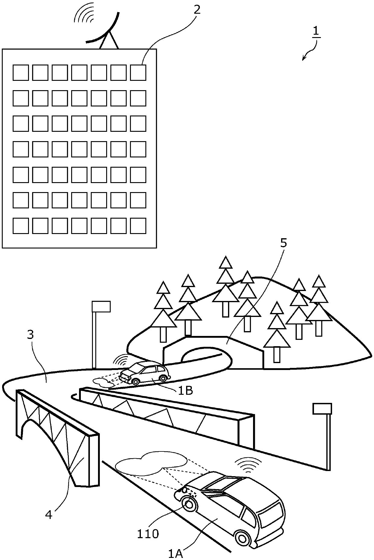
[0104] figure 1 It is a schematic diagram showing the outline of the road surface state prediction system 1 according to the first embodiment.
[0105] figure 1 A case where two mobile bodies 1A and 1B are traveling on a road 3 is schematically shown. The road 3 leads to the inside of the tunnel through the bridge 4 and the exit 5 of the tunnel. The mobile body 1A is about to pass through the bridge 4, and the mobile body 1B is coming out of the exit 5 of the tunnel.
[0106] The mobile bodies 1A and 1B are, specifically, vehicles such as four-wheeled vehicles and two-wheeled vehicles, and travel on the road 3 . Furthermore, at least one of the mobile bodies 1A and 1B may be a flying body called a drone.
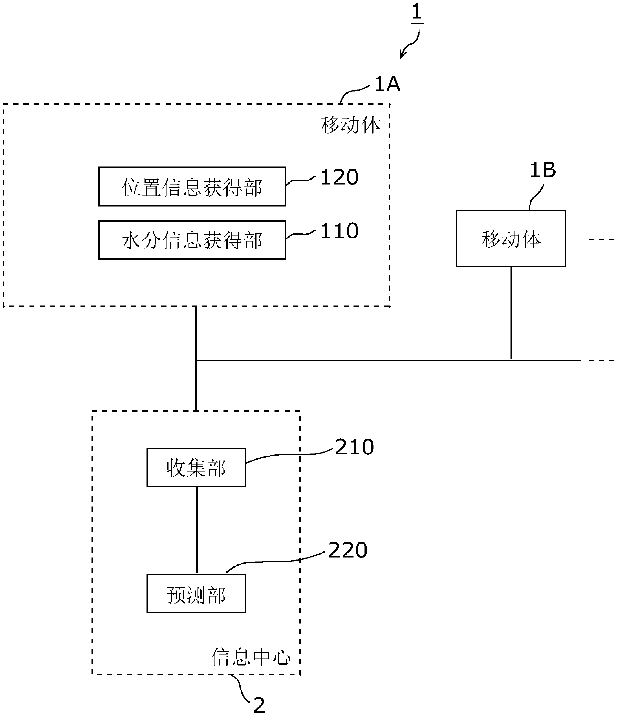
[0107] The mobile objects 1A and 1B detect moisture on the road surface of the road 3 while traveling on the road 3 to obtain moisture information related to the moisture on the road surface. The mobile bodies 1A and 1B communicate with the information center 2 wireless...
Embodiment approach 2
[0243] Next, for the road surface state prediction system according to Embodiment 2, use Figure 13 Be explained.
[0244] Figure 13 It is a block diagram showing the configuration of the road surface state prediction system 301 according to this embodiment.
[0245] Such as Figure 13 Shown, the road surface state prediction system 301, and figure 2 Compared with the illustrated road surface state prediction system 1 , the distribution unit 370 is newly provided. Specifically, the information center 2 includes a distribution unit 370 .
[0246] The distribution unit 370 distributes distribution information including the prediction result of the prediction unit 220 . The purpose of distribution is a vehicle in motion, a road manager, a traffic manager, a traffic information operator, a transportation operator, or a postal operator, etc.
[0247] For example, when receiving a distribution request from a distribution destination, the distribution unit 370 distributes dis...
Embodiment approach 3
[0254] Next, for the road surface state prediction system according to Embodiment 3, use Figure 14 Be explained.
[0255] Figure 14 It is a block diagram showing the configuration of the road surface state prediction system 302 according to this embodiment.
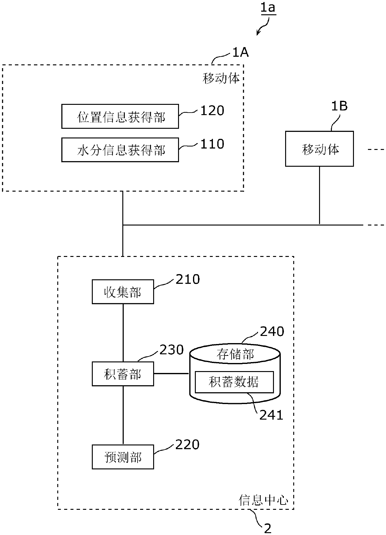
[0256] Such as Figure 14 Shown, the road surface state prediction system 302, and Figure 4 Compared with the road surface state prediction system 1b shown, the difference is that a distribution unit 370 , a notification unit 380 , a determination unit 381 , and a search unit 382 are newly provided. and, Figure 14 The illustrated mobile body 1A may also include an environmental information obtaining unit 130 .
[0257] Such as Figure 14 It is shown that in the road surface state prediction system 302, the distribution unit 370 of the information center 2 distributes the distribution information to the plurality of mobile bodies 1C and 1D. The mobile bodies 1C and 1D are mobile bodies that do not have the functio...
PUM
 Abstract
Description
Claims
Application Information
 - R&D Engineer
- R&D Manager
- IP Professional
- Industry Leading Data Capabilities
- Powerful AI technology
- Patent DNA Extraction
Browse by: Latest US Patents, China's latest patents, Technical Efficacy Thesaurus, Application Domain, Technology Topic.
© 2024 PatSnap. All rights reserved.Legal|Privacy policy|Modern Slavery Act Transparency Statement|Sitemap