Supercharge Your Innovation With Domain-Expert AI Agents!

Rapid anaerobic fermentation system

An anaerobic fermentation and rapid technology, applied in the field of biogas, can solve the problems of easy crusting of fermentation tanks, waste of time in fermentation time, crop damage, etc., and achieve the effects of wide application range, improvement of fermentation degree, and improvement of fermentation efficiency.

Pending Publication Date: 2019-04-30
中国农业大学烟台研究院
View PDF7 Cites 0 Cited by
  • Summary
  • Abstract
  • Description
  • Claims
  • Application Information

AI Technical Summary

Problems solved by technology

However, the traditional anaerobic fermentation devices for organic waste generally have the following deficiencies: the organic waste is inside the anaerobic fermentation device, and the fermentation time in cold seasons is too long to waste time, and part of the biogas slurry is not completely fermented, causing it to contain live bacteria and eggs. When used, it will cause damage to crops; in addition, the biogas residue in the prior art is not easy to discharge, and if it is not cleaned up, it will easily cause problems such as crusting in the fermentation tank for a long time

Method used


Image

  • Rapid anaerobic fermentation system
  • Rapid anaerobic fermentation system
  • Rapid anaerobic fermentation system

Examples


Embodiment 1

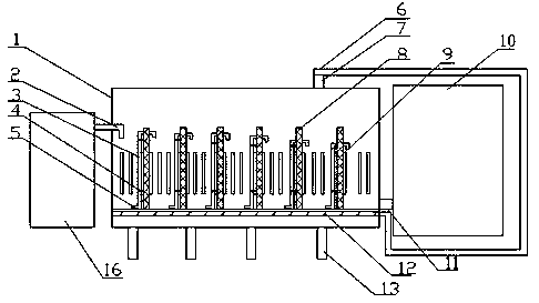
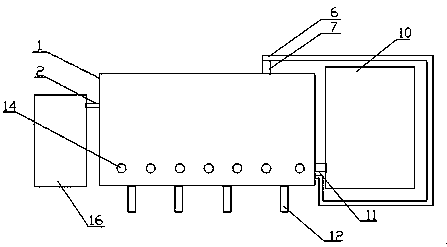
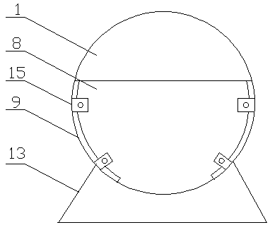
[0034] Such as figure 1 --A fast anaerobic fermentation system shown in 3, comprising: wet and dry separator 16, horizontal fermenter 1 and soft liquid storage tank 10, wherein: the two ends of the horizontal fermenter 1 are respectively provided with sewage Inlet 2 and liquid outlet 11, the rice end of the sewage inlet goes deep below the biogas liquid level to prevent biogas from overflowing, the dry-wet separator 16 is connected to the sewage inlet 2, and the liquid outlet is connected to the soft liquid storage pool 10, The interior of the horizontal fermenter 1 is divided into multiple chambers through a plurality of partitions 8 whose height is lower than that of the horizontal fermenter 1, but the upper part of the fermenter is still a cavity, and each partition 8 is passed through the first A fixing piece 4 fixes the biogas slurry pipe 3, and the biogas slurry pipe 3 extends from the bottom end of the partition plate 8 to the top and penetrates into the adjacent chambe...


PUM


Abstract

The invention discloses a rapid anaerobic fermentation system, and belongs to the technical field of biogas. The system comprises a dry-wet separator, a horizontal fermentation tank, and a soft liquidstorage tank. Two ends of the horizontal fermentation tank are respectively provided with a sewage inlet and a liquid outlet. The dry-wet separator is connected to the sewage inlet. The liquid outletis connected to the soft liquid storage tank. The interior of the horizontal fermentation tank is divided into a plurality of cavities by a plurality of partition plates, the height of the partitionplates is lower than the height of the horizontal fermentation tank, thus the upper part of the horizontal fermentation tank is still a cavity; a biogas fluid pipe is fixed on each partition plate, each biogas fluid pipe extends from the bottom end of corresponding partition plate to the top end and stretches into a neighbored cavity; and a hot water circulation pipe is paved on the bottom of thehorizontal fermentation tank and is connected to a biogas outlet in the horizontal fermentation tank through a biogas combustion heating system. The horizontal fermentation tank is adopted, the hot water circulation pipe is arranged on the bottom of the fermentation tank, thus the temperature of the biogas fluid in the fermentation tank is maintained in a certain range, the front end of the fermentation tank is connected to the blow-off pipes of farms, the interior of the fermentation tank is divided into a plurality of cavities by the partition plates, the fermentation time is enough, at thesame time, the discharge of organic wastes is not delayed, the fermentation efficiency and fermentation degree are improved, and the system provides nutrients for the growth of crops and does not damage the crops.

Description

technical field [0001] The invention belongs to the technical field of biogas, in particular to a rapid anaerobic fermentation system. Background technique [0002] Artificial breeding is an important way to meet market demand. In the breeding of livestock, in order to facilitate management and feeding, captive breeding is generally adopted. During the breeding process, a large amount of organic waste such as feces will inevitably be produced. The organic matter in these solid wastes decomposes to produce a large amount of pollutants, which is harmful to urban water bodies and soils. Air pollution is more serious. [0003] The traditional treatment method is mainly composting, and the direct composting of organic waste occupies a large area, has a serious odor and pollutes the environment. With the strengthening of the country's environmental protection, the advancement of domestic waste classification and the rapid growth of domestic demand for clean energy, organic waste...

Claims


Application Information

Patent Timeline
IPC IPC(8): C12M1/107C12M1/02C02F11/04
CPCC02F11/04C12M21/04C12M23/34C12M23/46C12M23/48C12M29/14C12M41/24C12M45/04
Inventor 孔凡克董仁杰丁世友鞠鑫鑫曲威于立芝刘曙光孔睿敏朱应民徐文彬刘玉华李海涛于海孔凡虎唐志鹏石万华王德冰崔国玉袁文杰孙绍霞
Owner 中国农业大学烟台研究院
Features
  • R&D
  • Intellectual Property
  • Life Sciences
  • Materials
  • Tech Scout
  • Unparalleled Data Quality
  • Higher Quality Content
  • 60% Fewer Hallucinations
Learn More