Humidification device for aquatic feed making machine through atomization, diversion, rotation and dispersion

A humidification device and aquaculture feed technology, applied in feed, food science, application and other directions, can solve the problems of mildew, low utilization rate of wet airflow, affecting work efficiency, etc., and achieve the effect of preventing mildew

Active Publication Date: 2021-12-07
台州市记顺泵业有限公司
View PDF9 Cites 0 Cited by
  • Summary
  • Abstract
  • Description
  • Claims
  • Application Information

AI Technical Summary

Problems solved by technology

[0002] The current feed humidification device usually mixes wind and water in a closed space, atomizes the water flow and sprays it out with the help of airflow to humidify the feed that enters through the conveyor belt, but in this way way can easily lead to:
[0003] When performing humidification work, the mixed wet airflow added to the inside of the confined space is easy to diffuse inside the space, so that the feed inside the airflow has not been humidified to rise in the opposite direction, or only the surface of the feed is humidified, so it is difficult to make the feed evenly humidified , and makes the utilization rate of the wet air flow low, and usually uses hot water as the medium. After being atomized into gas, when the internal temperature drops at the same time, the internal gas will condense inside the equipment, causing mildew, and at the same time Through the one-way conveying of the conveyor belt, the feed is affected by moisture, agglomerates, and condenses after drying, which makes the subsequent pressing work difficult and affects work efficiency

Method used


Image

  • Humidification device for aquatic feed making machine through atomization, diversion, rotation and dispersion
  • Humidification device for aquatic feed making machine through atomization, diversion, rotation and dispersion
  • Humidification device for aquatic feed making machine through atomization, diversion, rotation and dispersion

Examples


Embodiment

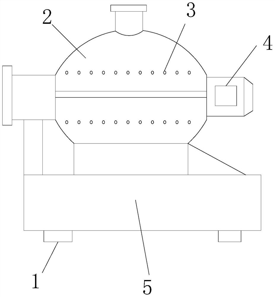
[0027] see figure 1 , the present invention provides a humidifying device for an aquatic feed making machine through atomization, diversion, rotation, and dispersion. The structure includes: a support pad 1, an intelligent humidifying device 2, a water outlet 3, a power motor 4, and a fixed base 5. The right end surface of the intelligent humidifying device 2 is fixedly connected with the intelligent humidifying device 2, the water outlet hole 3 is set on the outer end surface of the intelligent humidifying device 2 and is fixedly connected with the intelligent humidifying device 2 at the same time, and the fixed base 5 is located at the intelligent humidifying device 2 and is fixedly connected with the intelligent humidifying device 2, the support pad 1 is set on the lower surface of the fixed base 5 and is fixedly connected with the fixed base 5, the water outlet hole 3 is connected with the external water collecting device, through The connected water collection device can...


PUM


Abstract

The invention discloses a humidifying device for an aquatic feed making machine through atomization, diversion, rotation, and dispersion. The structure includes: a support pad, an intelligent humidifying device, a water outlet, a power motor, and a fixed base. The power motor is located on the right end surface of the intelligent humidifying device and It is fixedly connected with the intelligent humidification device. The outlet hole is set on the outer end face of the intelligent humidification device and is fixedly connected with the intelligent humidification device at the same time. Through the through-fitting of the internal arc tube and the dispersing tube, and connecting the dispersing tubes through small tubes, a certain The dispersing output pipeline, and the moisture inside the pipeline is synchronized, and is directly sprayed on the feed, and the movable shaft rotated by the power motor makes the dispersing frame stir so that the internal feed is repeatedly moved, so as to achieve the uniformity of the internal feed Humidification, while acting directly on the feed, can improve the efficiency of moisture use.

Description

technical field [0001] The invention relates to the field of aquatic feed production, in particular to a humidifying device for an aquatic feed manufacturing machine through atomization, diversion, rotation and dispersion. Background technique [0002] The current feed humidification device usually mixes wind and water in a closed space, atomizes the water flow and sprays it out with the help of airflow to humidify the feed that enters through the conveyor belt, but in this way way can easily lead to: [0003] When performing humidification work, the mixed wet airflow added to the inside of the confined space is easy to diffuse inside the space, so that the feed inside the airflow has not been humidified to rise in the opposite direction, or only the surface of the feed is humidified, so it is difficult to make the feed evenly humidified , and makes the utilization rate of the wet air flow low, and usually uses hot water as the medium. After being atomized into gas, when th...

Claims


Application Information

Patent Timeline
Patent Type & Authority Patents(China)
IPC IPC(8): A23N17/00
Inventor 邵书微周阳朱笔
Owner 台州市记顺泵业有限公司
Why Eureka
Try Eureka