
Automobile roof beam with bending resistance and manufacturing method thereof

A car roof and characteristic technology, which is applied in the field of auto parts manufacturing, can solve the problems of car roof deformation, no special design for safety, and inability to play the role of cushioning and shock absorption, so as to improve the effect of collision energy absorption and optimize materials Distribution, effect of good security effects

Inactive Publication Date: 2019-05-03
JILIN UNIV
View PDF8 Cites 3 Cited by
  • Summary
  • Abstract
  • Description
  • Claims
  • Application Information

AI Technical Summary

Problems solved by technology

[0003] The current body anti-deformation technology is mainly used for the front, side, and rear of the body, and no effective measures have been taken for the deformation of the roof
Although a general collision will not cause the roof to deform enough to injure the occupants, the vehicle often rolls due to the collision. At this time, there will be a large external force acting on the roof, which may cause a large deformation on the roof. deformation, and hurt the occupants, so it is very important to strengthen the safety protection of the roof
[0004] Under the current technology, the design of many car models only considers the supporting function of the roof beam, and there is no special design in terms of safety. The crossbeam is designed as a hollow steel thin-walled structure or a solid perforated steel plate structure, which cannot play a good role in buffering and shock absorption. This makes the accidents of casualties caused by roof deformation frequently occur when passenger cars roll over. occur

Method used


Image

  • Automobile roof beam with bending resistance and manufacturing method thereof
  • Automobile roof beam with bending resistance and manufacturing method thereof
  • Automobile roof beam with bending resistance and manufacturing method thereof

Examples


Embodiment Construction

[0032] In order to make the purpose, technical solutions and advantages of the embodiments of the present invention clearer, the technical solutions in the embodiments of the present invention will be clearly and completely described below in conjunction with the drawings in the embodiments of the present invention. Obviously, the described embodiments are only It is a part of embodiments of the present invention, but not all embodiments. The components of the embodiments of the invention generally described and illustrated in the figures herein may be arranged and designed in a variety of different configurations. Accordingly, the following detailed description of the embodiments of the invention provided in the accompanying drawings is not intended to limit the scope of the claimed invention, but merely represents selected embodiments of the invention. Based on the embodiments of the present invention, all other embodiments obtained by those skilled in the art without making...


PUM

PropertyMeasurementUnit
thicknessaaaaaaaaaa
thicknessaaaaaaaaaa
thicknessaaaaaaaaaa

Abstract

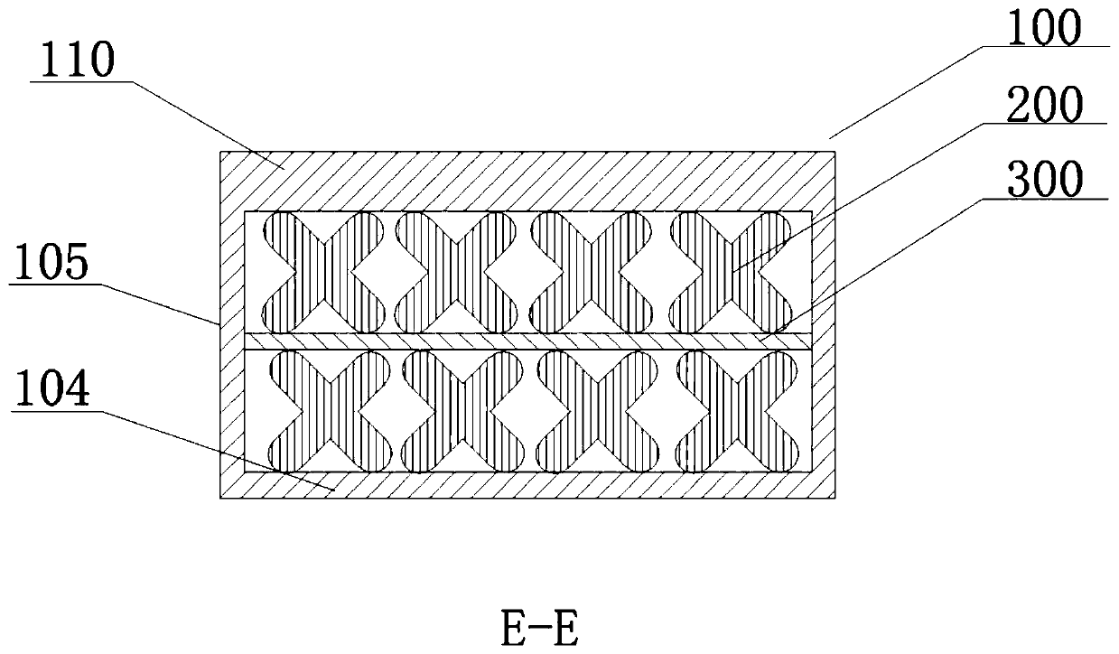
The invention relates to an automobile roof cover beam with bending resistance. The automobile roof cover beam with bending resistance includes a hollow beam made of carbon fibers, microstructured fillers and a carbon fiber laminate, wherein the microstructured fillers are bonded to the carbon fiber laminate and are arranged in the hollow beam; the hollow beam is a variable diameter square tube, and comprises an upper wall, a lower wall and left and right side walls; the upper wall is curved with a thick intermediate portion and two thin end portions; the cross section of the microstructured filler has a structure in which columnar bodies are intersected at one point, and two ends of the columnar body are semicircular; the microstructure is filled in the roof beam, so as to improve the impact energy absorption effect of the roof beam; and in order to enhance the rigidity of the roof beam, the carbon fiber composite material with high specific strength and high specific modulus is adopted, and is combined with the loading feature of the roof beam, the hollow beam adopts the structure with two thick sides and a thick intermediate portion, thus optimizing distribution of the material, improving the strength of the roof beam, thereby further obtaining a good safety effect.

Description

technical field [0001] The invention relates to the field of automobile parts manufacturing, in particular to an automobile roof beam with anti-bending properties and a manufacturing method thereof. Background technique [0002] With the popularization of passenger cars, the safety of passenger cars has attracted increasing attention. The safety of automobiles is divided into active safety technology and passive safety technology. Among them, the active safety technology is mainly used to help drivers avoid traffic accidents before the collision of the vehicle, and the passive safety technology comes to the maximum after the collision of the car. Minimize the injury to the driver or occupant of the vehicle. [0003] Present anti-deformation technology of vehicle body is mainly used in the front part, side part, rear part of vehicle body, does not take effective measure for the deformation of roof. Although a general collision will not cause the roof to deform enough to inj...

Claims


Application Information

Patent Timeline
Patent Type & Authority Applications(China)
IPC IPC(8): B62D25/06B62D29/04B29C70/34B33Y80/00B29L31/30
Inventor 马芳武支永帅杨猛蒲永锋王晓军梁鸿宇
Owner JILIN UNIV
Learn More