
Tunnel protective door system capable of fireproofing and anti-knock

A technology for protective doors and tunnels, which is used in mining installations, mining equipment, earth-moving drilling, etc., can solve the problems of rough surface, corrosion, and easy falling off of adhesion of protective doors, and achieves a wide range of operating temperature and good chemical stability. , the effect of increasing the overall strength

Pending Publication Date: 2019-05-03
CHINA RAILWAY SIYUAN SURVEY & DESIGN GRP
View PDF19 Cites 0 Cited by
  • Summary
  • Abstract
  • Description
  • Claims
  • Application Information

AI Technical Summary

Problems solved by technology

[0004] 1. The way of coating the fire-resistant coating on the outside of the protective door is usually not very satisfactory, and the thickness is thick and heavy. When the air humidity in the tunnel is high and the adhesion force is not good under the action of the tunnel piston wind, it is easy to fall off and the corrosion is serious. ;
[0005] 2. The method of applying refractory coating on the outside of the protective door cannot enhance the tensile and bending performance of the protective door, and cannot play the role of resisting impact and strong tunnel piston wind on the protective door;
[0006] 3. Except for the coating on the surface of the protective door, there is no other protective layer for fire protection and explosion protection;
[0007] 4. The surface of the protective door is rough and the decoration is poor; the design of the lifting chain is not optimized enough

Method used


Image

  • Tunnel protective door system capable of fireproofing and anti-knock
  • Tunnel protective door system capable of fireproofing and anti-knock
  • Tunnel protective door system capable of fireproofing and anti-knock

Examples


Embodiment Construction

[0034] In order to make the object, technical solution and advantages of the present invention clearer, the present invention will be further described in detail below in conjunction with the accompanying drawings and embodiments. It should be understood that the specific embodiments described here are only used to explain the present invention, not to limit the present invention. In addition, the technical features involved in the various embodiments of the present invention described below can be combined with each other as long as they do not constitute a conflict with each other.

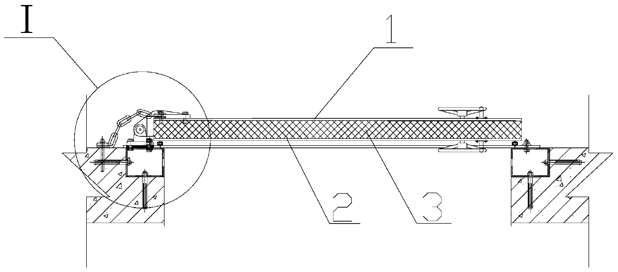
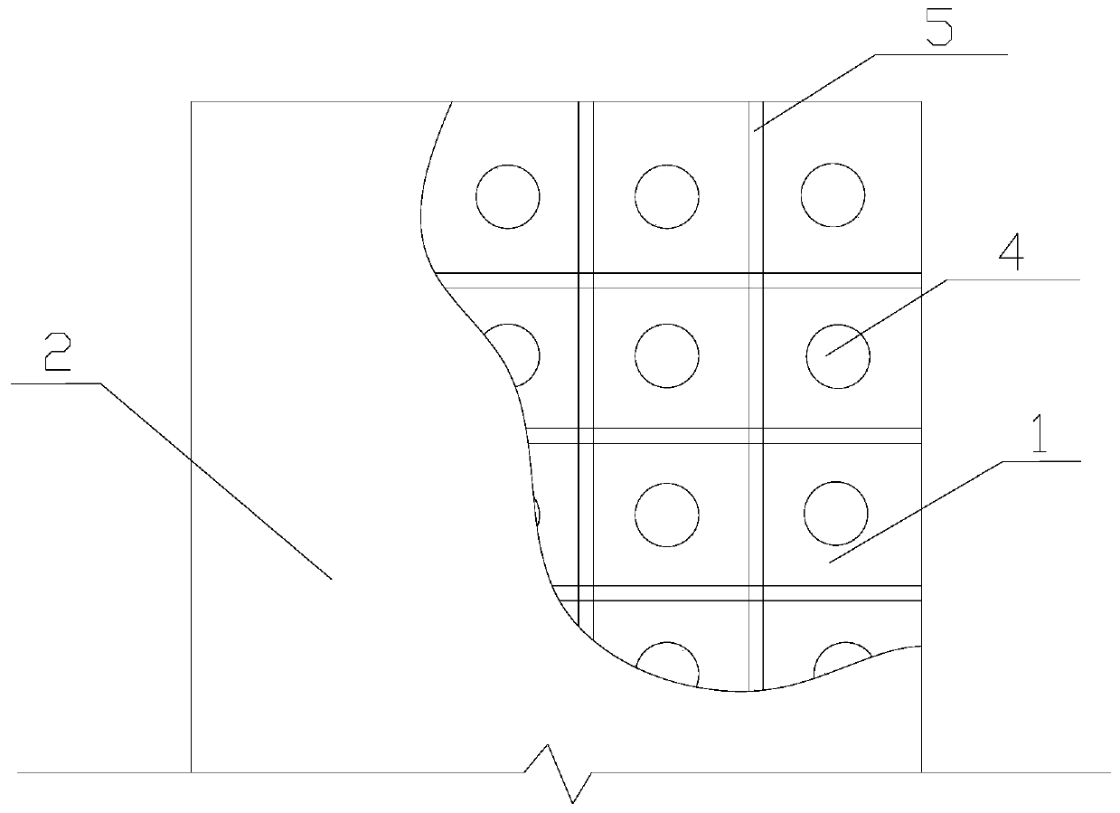
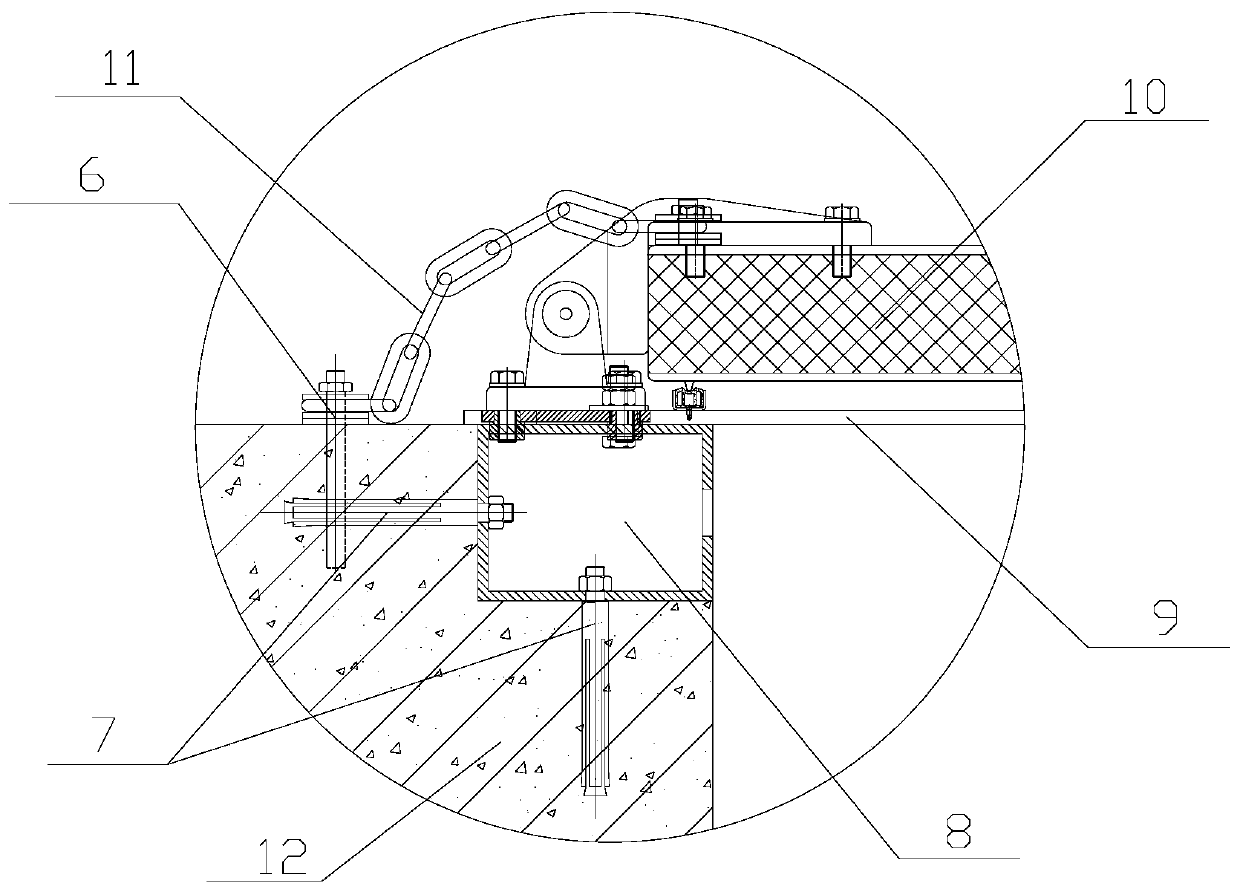
[0035] figure 1 It is a top view of a fireproof and anti-explosion tunnel protection door system according to the embodiment of the present invention Figure 1 ,Such as figure 1 As shown, the fireproof and anti-explosion tunnel protective door system involved in the present invention adopts a "sandwich type" door body interlayer structure, and the door leaf of the protective door includes a ca...


PUM


Abstract

The invention discloses a tunnel protective door system capable of fireproofing and anti-knock. The tunnel protective door system capable of fireproofing and anti-knock comprises a grotto side surfaceplate (1), a tunnel side surface plate (2) and a fire-resistant layer (3); steel trusses (5) are arranged between the grotto side surface plate (1) and the tunnel side surface plate (2) and are distributed in a longitudinal and horizontal staggered mode; the horizontal steel trusses and the longitudinal steel trusses (5) are respectively and fixedly connected with the grotto side surface plate (1) and the tunnel side surface plate (2), a plurality of filling space units are formed, all of the filling space units are respectively filled with fire-resistant materials, the fire-resistant layer (3) is formed between the grotto side surface plate (1) and the tunnel side surface plate (2), and thus a protective door system provided with a sandwich structure is formed. According to the tunnel protective door system capable of fireproofing and anti-knock, rigidity and intensity of the protective door is guaranteed through two layers of surface plates, good properties of heat insulation, fireresistant and anti-knock are provided through the fire-resistance layer materials, each filling space unit is individually filled with the fire-resistant materials through each filling hole respectively, and uniform stress of the whole is guaranteed.

Description

technical field [0001] The invention belongs to the technical field of railway tunnel protective doors, and more specifically relates to a fireproof and anti-explosion tunnel protective door system. Background technique [0002] With the development of my country's railway construction, especially the large-scale construction of passenger dedicated lines, the number and length of railway tunnels have increased year by year, and the fire prevention and rescue design problems of railway tunnels have become increasingly prominent. The newly revised "Fire Protection Code for Design of Railway Engineering" requires the installation of protective doors for cross passages and equipment caverns in tunnels of a certain length. Under disaster conditions, protective doors are of great significance for protecting cavern equipment, ensuring unimpeded information, crowd evacuation and creating escape conditions. [0003] At present, steel structures are usually painted with fire-resistan...

Claims


Application Information

Patent Timeline
Patent Type & Authority Applications(China)
IPC IPC(8): E21F17/12
Inventor 卫垚耿明张俊岭张浩邱绍峰刘辉史明红殷勤周明翔张银龙
Owner CHINA RAILWAY SIYUAN SURVEY & DESIGN GRP
Learn More