Ultra-wideband electromagnetic combination TEM horn antenna and parameter determination method thereof

A horn antenna and ultra-wideband technology, which is applied in the field of ultra-wideband electromagnetic combined TEM horn antenna and its parameters determination, can solve the problems of not using the TEM horn antenna, low high-frequency cut-off frequency, and affecting radar performance, etc., to improve low-frequency radiation Performance versus Time Domain Waveform, Intensity Enhancement, Effect of Improved Pattern

Inactive Publication Date: 2019-05-03
INST OF ELECTRONICS CHINESE ACAD OF SCI
View PDF4 Cites 8 Cited by
  • Summary
  • Abstract
  • Description
  • Claims
  • Application Information

AI Technical Summary

Problems solved by technology

[0005] The impedance bandwidth of the antenna with a VSWR of less than 2 is narrow, and the advantages of the TEM horn antenna itself are not brought into play. Usually, due to the discontinuity of the feed and the gradual change of the TEM horn curve based on the traditional exponential shape, the feed efficiency is not high and the high frequency The cut-off frequency is low; affected by the asymmetry of the end of the TEM horn's flare angle curve and the feed, the maximum radiation direction of the antenna is shifted to one side. When the electrical size increases to a normal TEM horn, the pattern shifts and the split flap characteristics are more It is obvious; in addition, time-domain analysis is extremely important for UWB antennas, and the smearing degree of transmitted time-domain signals will directly affect radar performance, and this problem is usually ignored

Method used


Image

  • Ultra-wideband electromagnetic combination TEM horn antenna and parameter determination method thereof
  • Ultra-wideband electromagnetic combination TEM horn antenna and parameter determination method thereof
  • Ultra-wideband electromagnetic combination TEM horn antenna and parameter determination method thereof

Examples


Embodiment Construction

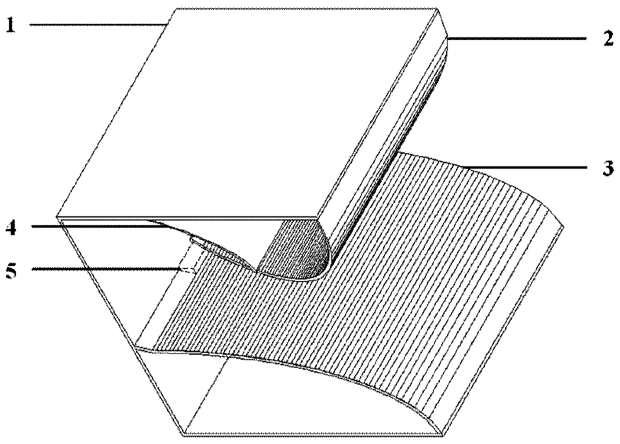
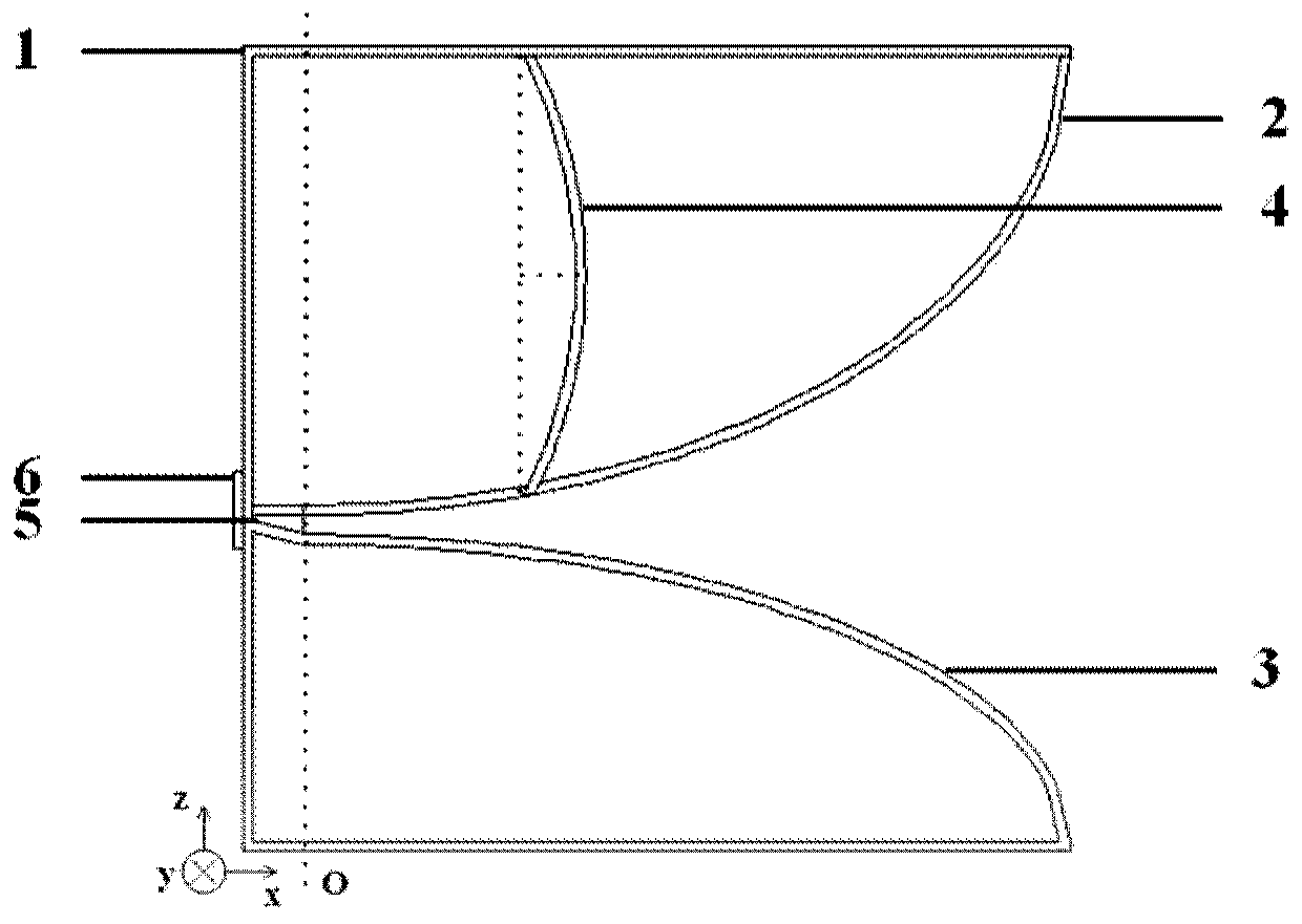
[0047] The invention adds an outer frame structure and an optimized arc-shaped parasitic metal branch to the TEM horn antenna, equivalent to more radiation structures, thereby significantly reducing the required size of the antenna with the radiation of the equivalent magnetic ring at the low frequency end. The antennas that improve theoretical performance by combining equivalent electromagnetic oscillators are collectively referred to as electromagnetic combined antennas.

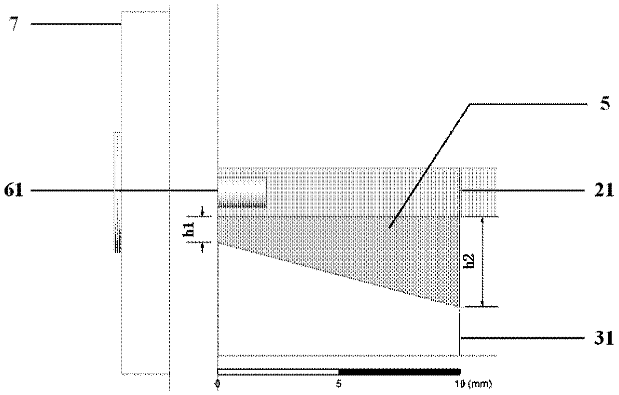
[0048]The present disclosure provides an ultra-broadband electromagnetic combined TEM horn antenna, which includes: a U-shaped square frame, a TEM horn upper arm, a TEM horn lower arm, and a dielectric spacer; a U-shaped square frame, including an upper frame, a lower frame and a supporting frame ;The upper frame and the lower frame are respectively connected through the support frame, and the support frame is provided with a boss; the SMA connector is arranged on the boss, and the current is fed into the T...


PUM


Abstract

The invention provides an ultra-wideband electromagnetic combination TEM horn antenna and a parameter determination method thereof. The ultra-wideband electromagnetic combination TEM horn antenna comprises a [-shaped square frame, a TEM horn upper arm, a TEM horn lower arm, a parasitic branch, a dielectric gasket, an SMA connector and a boss, wherein a current passes the SMA connector and is fed into the TEM horn antenna, a feed end of the TEM horn upper arm is connected with an inner core of the SMA connector, the dielectric gasket is filled between an upper arm transition section and a lowerarm transition section, the [-shaped square frame, the TEM horn upper arm and the parasitic branch enclose to form a closed magnetic ring, and the current flows through the parasitic branch to causeshunting. The ultra-wideband electromagnetic combination TEM horn antenna optimizes the high-frequency split lobe of the TEM antenna by adopting an upper and lower arm elliptical gradation manner, sothat the high-frequency gain is improved; the low-frequency radiation is enhanced by means of the arc-shaped parasitic branch, and the low-frequency bandwidth is expanded; the maximum radiation direction is adjusted by adopting the asymmetric design of heights of the upper and lower arms, so that the beam is kept in the x-axis direction; and the transition sections are used for replacing a balun,and the dielectric gasket is used for adjusting the transition impedance, so as to achieve the effect that the antenna bandwidth is greater than 20 octaves.

Description

technical field [0001] The disclosure relates to the field of ultra-wideband antenna design, in particular to an ultra-wideband electromagnetic combined TEM horn antenna and a parameter determination method thereof. Background technique [0002] For ultra-wideband antennas, there is a contradiction between size miniaturization and low-frequency cut-off frequency expansion. How to realize antenna miniaturization while ensuring the antenna bandwidth has always been the focus of UWB antenna research. [0003] UWB antennas are commonly used in the form of loaded dipole antennas, Bow-tie antennas, Vivaldi antennas, horn antennas, etc. Among them, the loaded dipole antenna has sufficient working bandwidth and is easy to design and process, but due to the loss of loading resistance, the efficiency It is low and has a very long size, so it cannot be used in arrays that require high portability. Bow-tie antennas are often used in shallow geological detection radars. Bow-tie antenna...

Claims


Application Information

Patent Timeline
Patent Type & Authority Applications(China)
IPC IPC(8): H01Q13/02H01Q1/36H01Q1/50
Inventor 纪奕才杨光耀阎焜刘新叶盛波张群英方广有
Owner INST OF ELECTRONICS CHINESE ACAD OF SCI
Why Eureka
Try Eureka